Method and apparatus for producing closed cell foam

a closed cell foam and foam technology, applied in the direction of flow mixers, mixing methods, mixers, etc., can solve the problems of significant drawbacks relating to cost effectiveness and practicality in certain applications, relatively difficult to set up, and large volume of mixers, so as to avoid the relatively high cost, improve the effect of homogeneity, and simplify the design and operation

Inactive Publication Date: 2005-05-05
NORDSON CORP
View PDF31 Cites 28 Cited by
  • Summary
  • Abstract
  • Description
  • Claims
  • Application Information

AI Technical Summary

Benefits of technology

[0017] The second stage mixer is configured to break these larger gas bubbles up into smaller gas bubbles, therefore becoming a homogeneous solution as defined herein. An advantageous aspect of the two-stage mixing device is that the dynamic mixer may take the form of a dynamic gear pump or disc mixer which is much simpler in design and operation as compared to the current dynamic mixers, such as those of the '631 patent. A heated hose may further be provided between the exit of the booster and the dispensing gun. The heated hose not only makes the material more flowable between the second stage mixer and the dispensing gun, but the heated hose also drives the gas further into solution providing a more homogenous solution and more consistent foam.
[0018] The two-stage mixing unit as described in the present invention has several advantages. For example, high quality closed cell foam coatings and beads may be applied using apparatus and methods of the present invention in many diverse applications while avoiding the relatively high cost associated with dynamic mixers currently in use. In particular, dynamic mixers used in the present invention do not utilize the expensive and complex mechanical face seals of previous dynamic mixers, but instead use cheaper, more reliable, and less complex lip seals. The present invention can be used to homogeneously mix gas into viscous liquid polymeric materials to form closed cell foams thus eliminating or significantly reducing major costs associated with the manufacture, repair, maintenance and clean up of prior dynamic mixers used to produce many of the same closed cell foams.

Problems solved by technology

The '631 patent addressed some of the shortcomings of gear pump mixers, especially with respect to the inability to obtain adequate mixing with polymers having viscosities above 50,000 cps, however, the dynamic mixers of the type disclosed in the '631 patent have significant drawbacks related to their cost effectiveness and practicality in certain applications.
Most notably, these mixers are relatively bulky and complex in design due to their large number of moving parts.
Therefore, they may be relatively difficult to set up especially where space considerations are a significant factor and, perhaps more importantly, are expensive to manufacture and therefore costly to the end user.
Also, the cost of maintenance and repair remains high throughout the life of the mixers due to their relatively complex design.
Although the device disclosed in the '529 patent performs satisfactorily when used in conjunction with many liquids, and specifically hot melt adhesives having much lower viscosities than the materials used in, for example the dynamic mixer of the '631 patent mentioned above, testing has shown that higher viscosity liquid polymers having viscosities above about 3,000 cps cannot be formed into high quality foams with the dispensing head of the '529 patent.
More specifically, when plastisols having viscosities on the order of 3,000 cps and above are run through the dispensing head disclosed in the '529 patent, inadequate dispersion of the gas within the plastisol results in low quality foam which is unsuitable for many applications.
Thus, the dispensing head of the '529 patent is not suited for producing the high quality foamed polymeric material which is produced by the dynamic mixer of the '631 patent mentioned above.
This design not only requires appreciable costs and appreciable space due to the large number of elements required to produce a high quality foam, but also requires the pressure of the liquid material to be significantly increased in order to push the liquid through the large number of mixing elements.

Method used


Image

  • Method and apparatus for producing closed cell foam
  • Method and apparatus for producing closed cell foam
  • Method and apparatus for producing closed cell foam

Examples


Embodiment Construction

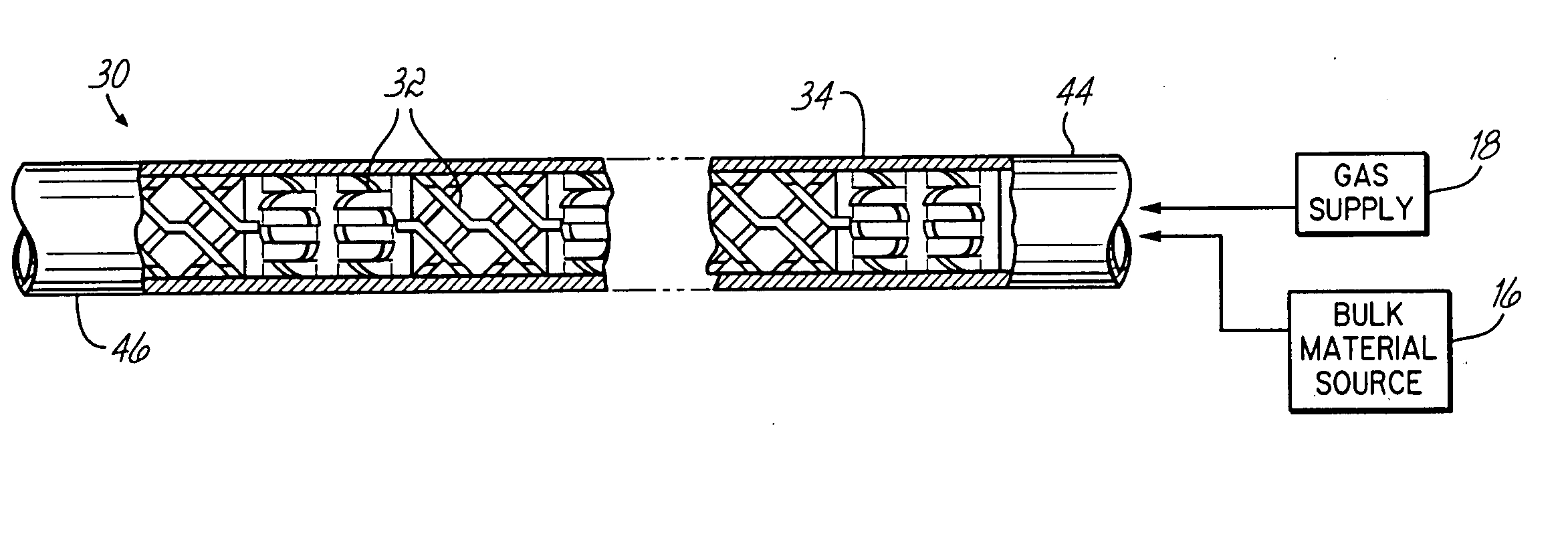
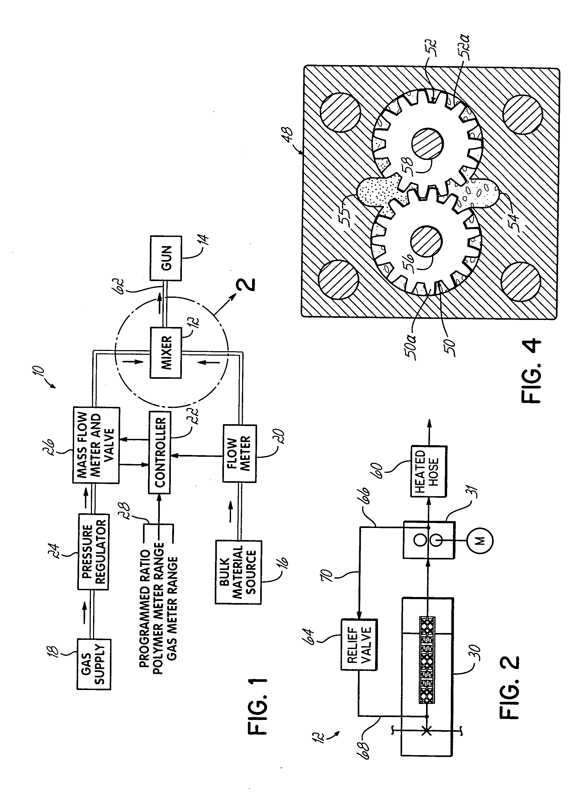
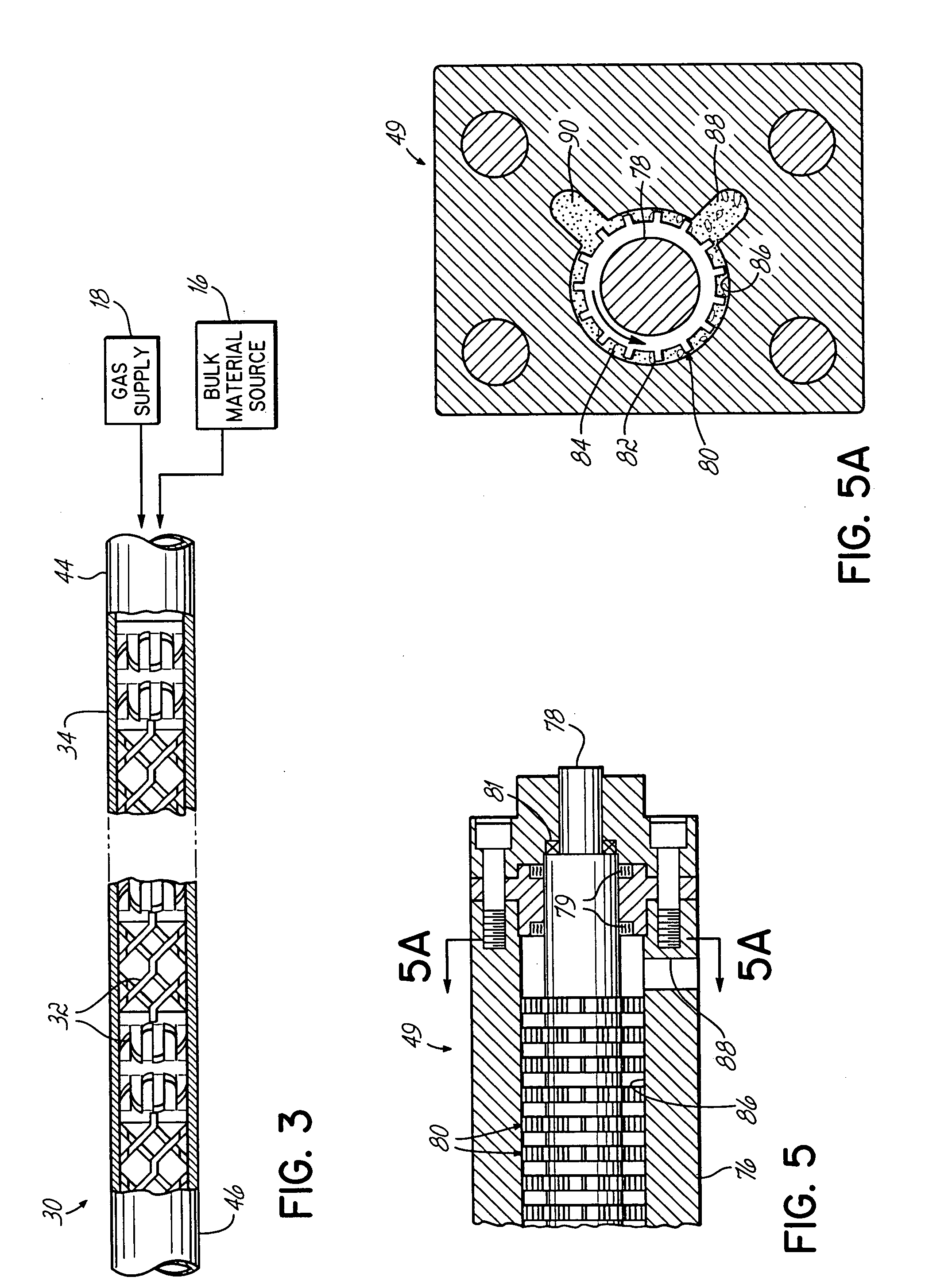
[0027] Referring to FIG. 1 a foam dispensing system 10 is illustrated and comprises a suitable system in which the mixing unit of the present invention may be incorporated. Except for mixing unit 12, the general configuration of the system 10 is shown and described in more detail in U.S. Pat. No. 5,056,034 issued to Rucki et al. and which is assigned to the assignee of the present invention and hereby incorporated by reference herein in its entirety. The system 10 controls gas and polymer flow to a mixing unit 12 constructed according to the present invention, as further explained below. The mixing unit 12 delivers a solution of the polymer and gas to a dispensing gun 14 after receiving and mixing liquid polymeric material and gas, respectively, from a bulk material source 16 and gas supply 18. The system 10 further includes a digital flow meter 20, a controller 22 as well as a pressure regulator 24 and a mass flow meter and valve 26. The digital flow meter 20 produces output pulses...


PUM

PropertyMeasurementUnit
pressureaaaaaaaaaa
viscositiesaaaaaaaaaa
temperaturesaaaaaaaaaa

Abstract

Methods and apparatus for producing high quality closed cell foams for use in applications such as coatings, sealant beads, seam filling and gaskets is provided. A two-stage mixing unit, having a static mixing stage comprising a static mixer having a plurality of mixing elements followed immediately by a second dynamic stage such as a dynamic gear pump or disc mixer is used to homogeneously disperse a gas throughout a highly viscous liquid polymeric material such as a plastisol, silicone, butyl or urethane based materials.

Description

[0001] This application claims the benefit of U.S. Provisional Application No. 60 / 516,368 filed on Oct.31, 2004, the disclosure of which is hereby incorporated by reference herein.FIELD OF THE INVENTION [0002] The present invention relates to methods and apparatus for mixing a gas with a liquid polymeric material to produce a closed cell foam structure such as a foam coating or bead. More particularly, the invention is suitable for use with polymeric materials such as adhesives, sealants and caulks. BACKGROUND OF THE INVENTION [0003] The assignee of this invention pioneered the development and application of methods and apparatus for foaming hot melt thermoplastic adhesives as well as other polymeric materials such as sealants and caulks. Hot melt adhesives are widely used throughout industry for adhering substrates one with another in many diverse applications, including the packaging and cartoning industries. With respect to hot melt adhesives, for example, the assignee of this in...

Claims


Application Information

Patent Timeline
Patent Type & Authority Applications(United States)
IPC IPC(8): B01F3/04B01F5/06B01F7/00B01F13/10B29B7/74
CPCB01F3/04453B01F5/0619B01F7/008B29B7/7409B01F2215/0468B01F2215/0495B01F13/1025B29B7/7419B29B7/72B29B7/7447B01F23/2351B01F25/43161B01F25/62B01F27/272B01F33/82
Inventor FOSTER, JOHN R. JR.VARGA, LESLIE J.
Owner NORDSON CORP
Why Eureka
Try Eureka