Method and apparatus for header compression

a header compression and data technology, applied in the field of header compression methods and apparatuses, can solve the problems of transmission errors, transmission errors are prone to occur, and the communication overhead is not suitable for wireless communication with a high transmission error rate, so as to improve the header compression efficiency and data transmission efficiency

Inactive Publication Date: 2005-05-05
PANASONIC INTELLECTUAL PROPERTY CORP OF AMERICA
View PDF4 Cites 48 Cited by
  • Summary
  • Abstract
  • Description
  • Claims
  • Application Information

AI Technical Summary

Benefits of technology

[0025] Therefore, an object of the present invention is to present how to switch the header compression scheme between the reliable mode and the optimistic mode, and provide a method and apparatus for header compression / decompression for improving the header compression efficiency and the data transmission efficiency during wireless transmission.

Problems solved by technology

In data transmission over a low and midrange bit rate transmission path, however, the added header specified by TCP, UDP, IP, or other protocols increases the packet size, thereby disadvantageously causing overhead associated with communication.
The Jacobson's header compression scheme is a standard for wired communication with a low transmission error rate, and is not suitable for wireless communication with a high transmission error rate.
In this network, however, transmission errors are prone to occur in a wireless transmission section 76, and therefore the Jacobson's header compression scheme does not effectively work.
However, the transmitting side continues to transmit the packets with the update information added thereto until receiving the ACK packet, thereby degrading header compression efficiency and entire data transmission efficiency.
However, if the data receiving apparatus 90 has not correctly received the update information due to transmission error, header decompression errors continuously occur until receiving the update information, thereby considerably degrading the data transmission efficiency.
However, how to switch the header compression scheme has been unclear so far.

Method used


Image

  • Method and apparatus for header compression
  • Method and apparatus for header compression
  • Method and apparatus for header compression

Examples


first embodiment

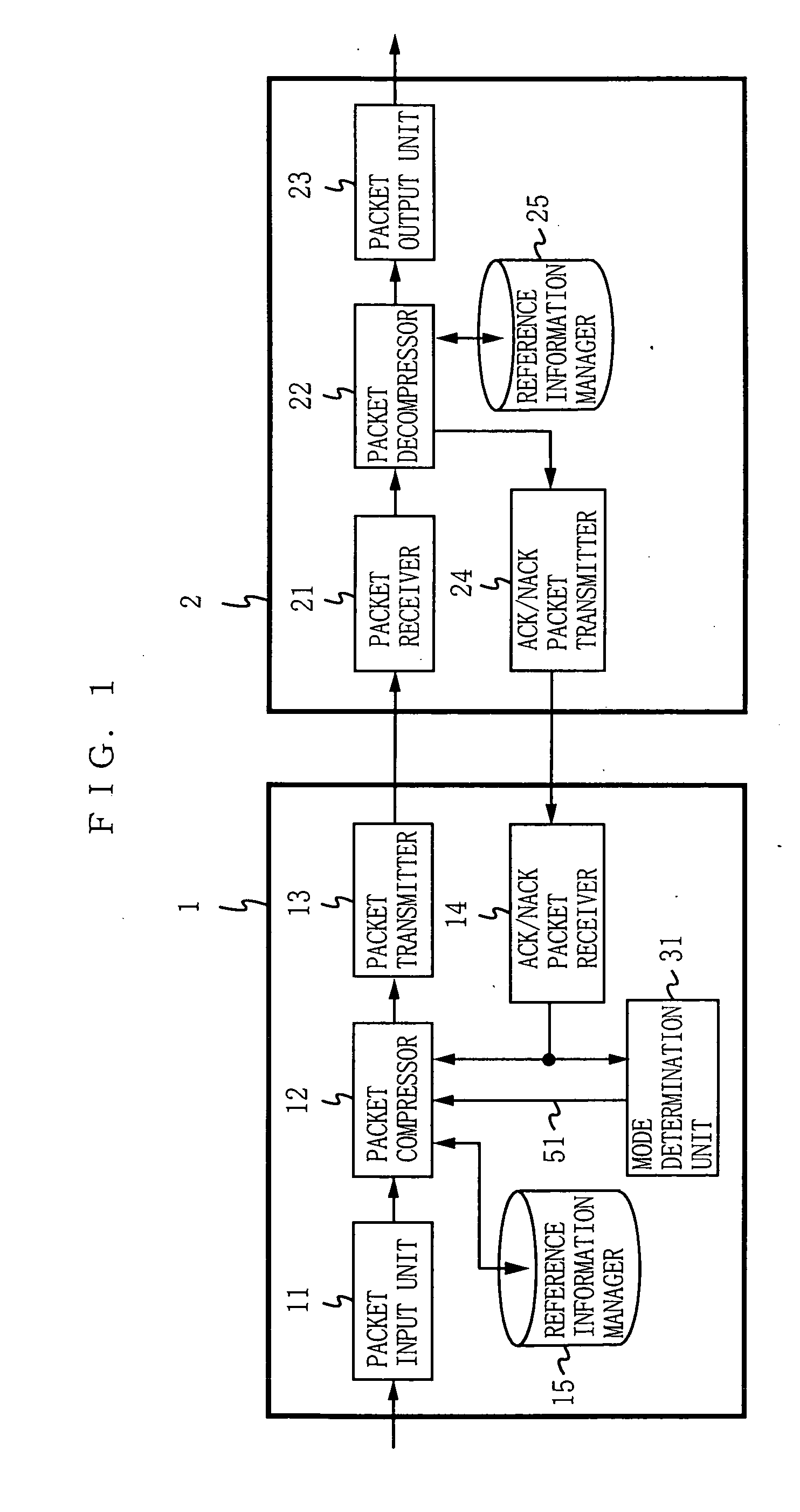
[0073]FIG. 1 is a data transmitting apparatus and a data receiving apparatus according to a first embodiment of the present invention. In FIG. 1, a data transmitting apparatus 1 includes a packet input unit 11, a packet compressor 12, a packet transmitter 13, an ACK / NACK packet receiver 14, a reference information manager 15, and a mode determination unit 31. A data receiving apparatus 2 includes a packet receiver 21, a packet decompressor 22, a packet output unit 23, an ACK / NACK packet transmitter 24, and a reference information manager 25.

[0074] The reference information manager 15 and the reference information manager 25 each store and manage the same reference information. Here, the reference information is information indicating a change in each field included in the header of the packet from the one included in the header of the previous packet. The reference information stored in the reference information manager 15 is referred to for compressing the header of the packet. Th...

example modification

of First Embodiment

[0090] In the first embodiment, the unit time X referred to by the mode determination unit 31 does not have any limitation. Therefore, the value of the unit time X may be dynamically varied depending on the number of ACK packets or NACK packets received.

[0091] The mode determination unit according to one example modification of the first embodiment counts the number of ACK packets or NACK packets received, and also divides the counted number by the number previously counted, thereby calculating the rate of change in the number of received packets. When the calculated rate of change is smaller than a predetermined value A, the mode determination unit determines that the transmission quality is stable, and increases the value of the unit time X. On the other hand, when the calculated rate of change is larger than a predetermined value B, the mode determination unit determines that the transmission quality is frequently varied, and decreases the value of the unit ti...

second embodiment

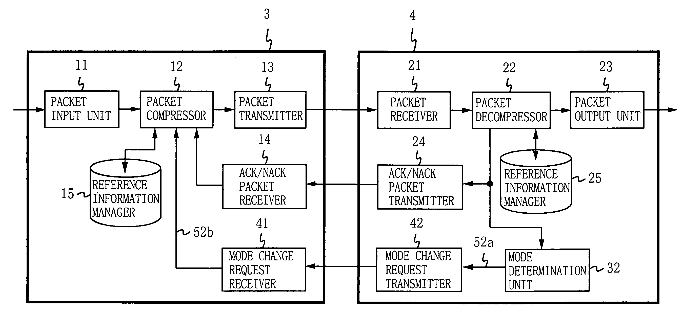
[0093]FIG. 3 is a block diagram showing the structure of a data transmitting apparatus and a data receiving apparatus according to a second embodiment of the present invention. In FIG. 3, a data transmitting apparatus 3 includes a mode change request receiver 41, and a data receiving apparatus 4 includes a mode determination unit 32 and a mode change request transmitter 42. In the second embodiment, the data receiving apparatus 4 determines the switching of the header compression scheme, which is different from the first embodiment where the data transmitting apparatus 1 determines the switching. In the second embodiment, components that are the same as those in the first embodiment are provided with the same reference numerals, and not described herein.

[0094] When detecting any header decompression error, the packet decompressor 22 also notifies the mode determination unit 32 of the error. The mode determination unit 32 counts the number of header decompression errors that occurre...


PUM


Abstract

A packet compressor 12 operates under a reliable mode or an optimistic mode. A mode determination unit 31 counts the number of ACK packets or NACK packets received by a unit time X by an ACK / NACK packet receiver 14. When the counted number of NACK packets is larger than a predetermined value Y, the mode determination unit 31 switches the operation mode of the packet compressor 12 to the reliable mode. When the counted number of ACK packets is larger than a predetermined value Z, the mode determination unit 31 switches the operation mode of the packet compressor 12 to the optimistic mode.

Description

BACKGROUND OF THE INVENTION [0001] 1. Field of the Invention [0002] The present invention relates to methods and apparatuses for data compression and, more specifically, to a method and apparatus for header compression / decompression used in a data transmission system where a packet is compressed in a transmitting side and decompressed in a receiving side. [0003] 2. Description of the Background Art [0004] Typical protocols recently known for data transmission over the Internet include TCP / IP (Transmission Control Protocol / Internet Protocol) and UDP / IP (User Datagram Protocol / Internet Protocol). One protocol known for real-time transmission of data such as audio and images under TCP / IP or UDP / IP is RTP (Realtime Transport Protocol) , which is described in detail in “RTP: A Transport Protocol for Real-Time Applications”, H. Schulzrinne, S. Casner, R. Frederik, and V. Jacobson, RFC1889, 1996. [0005] When data is transmitted by unit of a packet in compliance with the protocols such as T...

Claims


Application Information

Patent Timeline
Patent Type & Authority Applications(United States)
IPC IPC(8): H04L1/00H03M7/30H04L1/16H04L1/18H04L69/40
CPCH04L1/0001H04L1/0078H04L69/22H04L69/04H04L1/1809
Inventor HATA, KOICHIMIYAZAKI, AKIHIROIMURA, KOJIIDO, DAIJI
Owner PANASONIC INTELLECTUAL PROPERTY CORP OF AMERICA
Why Eureka
Try Eureka