
Electrical thermometer

a technology of electric thermometers and thermometers, applied in the field of electric thermometers, can solve the problems of high manufacturing cost of conventional electrical thermometers, no significant effect of features on heat equilibrium, and high cost of new materials and development expenses, and achieve the effect of rapid heat equilibrium and accelerated measurement tim

Inactive Publication Date: 2005-05-05
ORIENTAL SYST TECH
View PDF9 Cites 29 Cited by
  • Summary
  • Abstract
  • Description
  • Claims
  • Application Information

AI Technical Summary

Benefits of technology

[0009] An objective of the present invention is to provide an electrical thermometer that attains heat equilibrium rapidly. A thermal sensor is immersed in thermally conductive glue, which is positioned at the front inner end of a metallic tip. The remaining space within the metallic tip is filled up with a good thermal insulator. With such a design, the heat generated by human body can be rapidly transferred to the thermal sensor by the thermally conductive glue, meanwhile the thermal insulator can prevent the heat from being transferred to other materials that can absorb heat so as to accelerate the measurement time.
[0010] In order to achieve the objective, the present invention discloses an electrical thermometer that comprises a metallic tip and a main body equipped with a probe portion. The front end of the probe portion is fitted into the opening of the metallic tip, which resembles a shell with a blunt end. The probe portion is formed on the main body. A thermal sensor, which is immersed and fixed in thermally conductive glue, is positioned inside the front inner end of the metallic tip. The remaining space within the metallic tip is filled up with a good thermally insulator. The metallic tip can be rapidly heated up with body temperature whenever touched, and the heat will be transferred to the thermal sensor via the thermally conductive glue. In additional, the thermally insulator can stop succeeding heat transfer.

Problems solved by technology

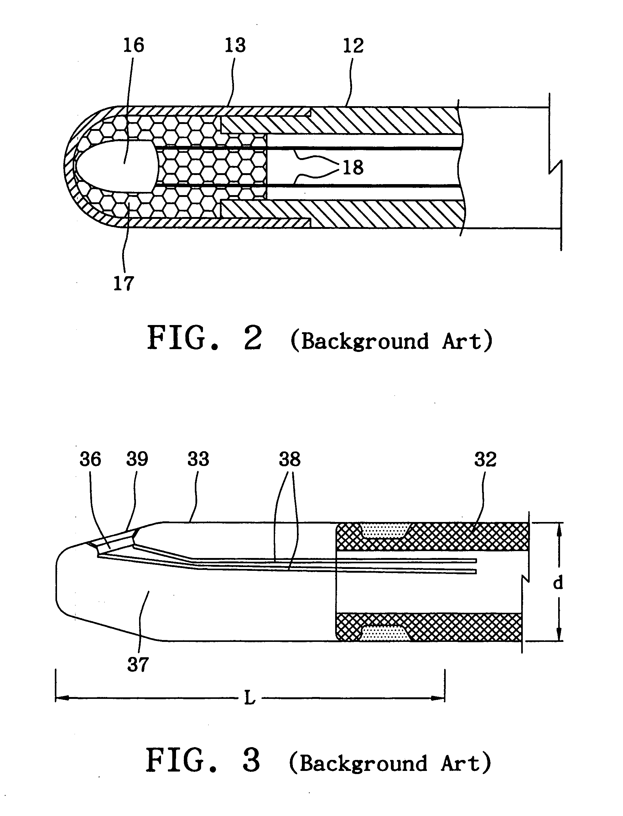
However, such a feature does not have any significant effect on the heat equilibrium, because the cross-sectional areas of the electrically conductive wires 18 are extremely small and the probe portion 12 is a good heat insulator.
First, it specifies the metallic tip 33 of with a particular size, thus the existing metallic tips and probe portions cannot be applied to it; hence, it requires new materials and development expenses for related producing die.
Second, the metallic tip 33 is bulky, thus the manufacturing cost of the conventional electrical thermometer is high.

Method used


Image

  • Electrical thermometer
  • Electrical thermometer
  • Electrical thermometer

Examples


Embodiment Construction

[0018]FIG. 4 is a perspective diagram of an electrical thermometer in accordance with the present invention. An electrical thermometer 40 comprises a main body 41 to be held by hand. The main body 41 is equipped with a tapered probe portion 42, thus it is easy to put the probe portion 42 and a metallic tip 43 mounted on its front end under a human being's armpit or into one's oral cavity or anus. In general, the main body 41 and the probe portion 42 are made from a heat insulating plastic material and are formed together in one single piece. The metallic tip 43, which appears in the form of a shell with a blunt tip, is fabricated by stamping a metal sheet. The front end of the probe portion 42 is fitted into the opening of the metallic tip 43.

[0019] A display unit 44 is installed on the main body 41 for users to easily read measurement data. A switch 45 is also installed on the main body 41 for users to trigger an internal circuit intended for a measurement action. The display unit...


PUM


Abstract

An electrical thermometer comprises a metallic tip and a main body equipped with a probe portion. The front end of the probe portion is fitted into the opening of the metallic tip, which resembles a shell with a blunt end. The probe portion is formed on the main body. A thermal sensor, which is immersed and fixed in thermally conductive glue, is positioned inside the front inner end of the metallic tip. The remaining space within the metallic tip is filled up with a good thermally insulator. The metallic tip can be rapidly heated up with body temperature whenever touched, and the heat will be transferred to the thermal sensor via the thermally conductive glue. In additional, the thermally insulator can stop succeeding heat transfer.

Description

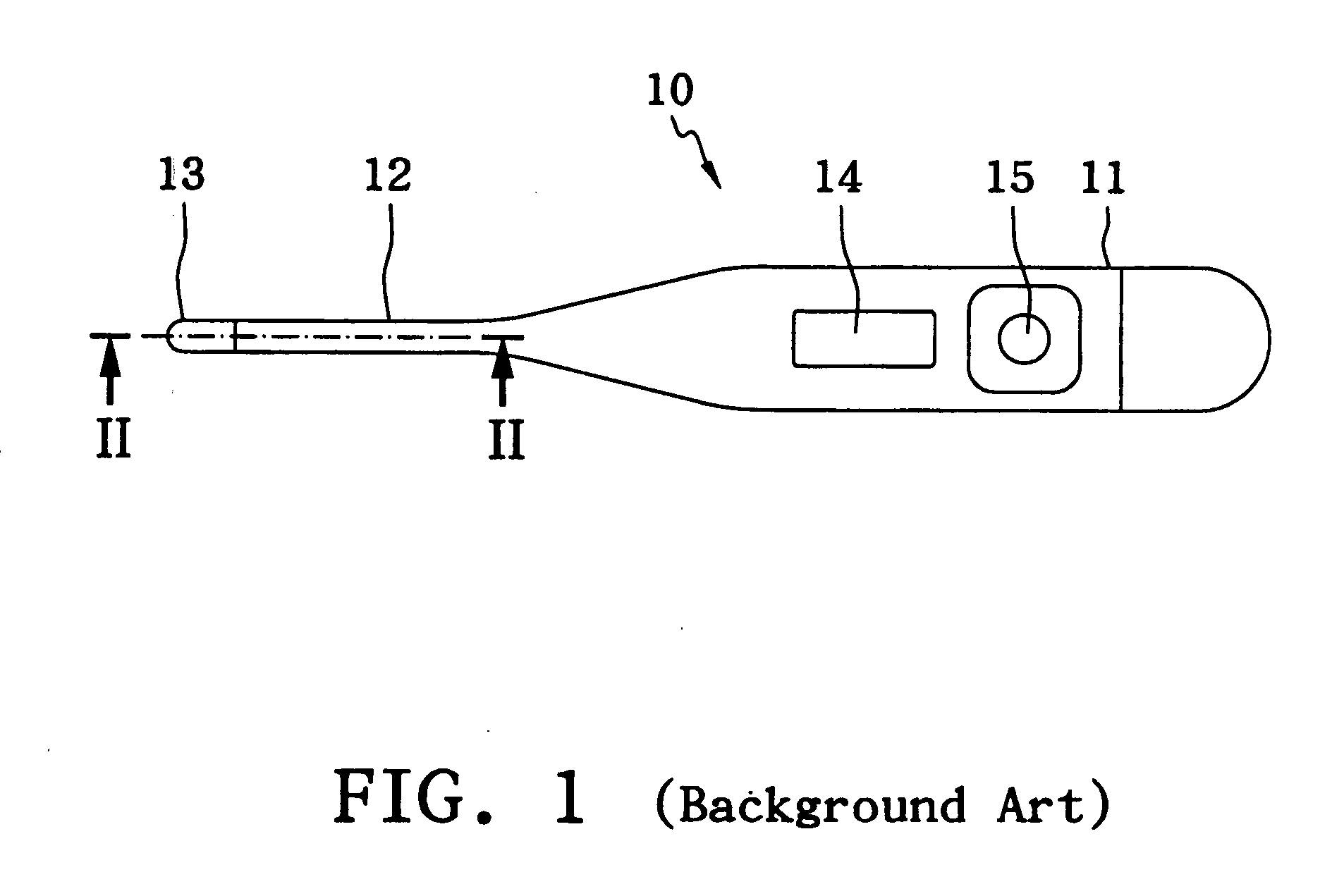
RELATED U.S. APPLICATIONS [0001] Not applicable. STATEMENT REGARDING FEDERALLY SPONSORED RESEARCH OR DEVELOPMENT [0002] Not applicable. REFERENCE TO MICROFICHE APPENDIX [0003] Not applicable. FIELD OF THE INVENTION [0004] The present invention relates to an electrical thermometer intended to take human body temperature and more particularly to an electrical thermometer that attains thermal equilibrium rapidly. BACKGROUND OF THE INVENTION [0005] Conventional mercury-based thermometers have plenty of shortcomings. By contrast, electrical thermometers are widely used in taking human body temperature for clinical purposes because it is safe, fast and easy to take body temperature with an electrical thermometer. A known electrical thermometer 10 comprises a main body 11 to be held by hand. The main body 11 is equipped with a tapered probe portion 12 as shown in FIG. 1. A metallic tip 13 is positioned at the front end of the probe portion 12. The metallic tip 13 can rapidly transfer heat ...

Claims


Application Information

Patent Timeline
IPC IPC(8): G01K7/00G01K13/00
CPCG01K13/002G01K13/20
Inventor LEE, HERMANCHANG, SHUN-CHIN
Owner ORIENTAL SYST TECH
Learn More