Geophysics-based method of locating a stationary earth object

a stationary earth object and geophysics technology, applied in the field of geolocation, can solve the problems of slow moving objects affecting the performance of imu, navigation errors may accumulate at rates as high as kilometers per hour, and achieve the effect of improving with measurement tim

Active Publication Date: 2008-05-20
NAT TECH & ENG SOLUTIONS OF SANDIA LLC
View PDF3 Cites 82 Cited by
  • Summary
  • Abstract
  • Description
  • Claims
  • Application Information

AI Technical Summary

Benefits of technology

[0011]On the contrary, performance of the geophysics-based position location method of the present invention improves with measurement time. As a result, the method is particularly useful for tracking intermittently-moving objects in GPS-denied environments. Examples of such objects are ground vehicles and shipping containers. Other objects that move only occasionally also fall into this category, such as office equipment, computer systems, missile launchers, and other high-value assets. It is anticipated that in many situations involving stationary high-value assets, access to sky or terrestrial beacons will be denied for long periods of time, such as may be the case in subterranean storage locations. In fact, just about everything that moves also spends most of its time sitting still for at least hours at a time. By determining the location of an object during the times it is stationary and keeping track of when movement started and stopped, the method of the present invention can track intermittently moving objects anywhere on or near the surface of the earth's land masses. The method requires no external infrastructure and no foreknowledge of how the object might be moved, such as would be required using GPS or an aided IMU approach.

Problems solved by technology

However, if GPS is not available, IMU performance degrades rapidly with slow moving objects, due to accumulated measurement drift.
Simulations with perfect sensors suggest that the resulting navigation errors may accumulate at rates of as high as kilometers per hour.

Method used


Image

  • Geophysics-based method of locating a stationary earth object
  • Geophysics-based method of locating a stationary earth object
  • Geophysics-based method of locating a stationary earth object

Examples


Embodiment Construction

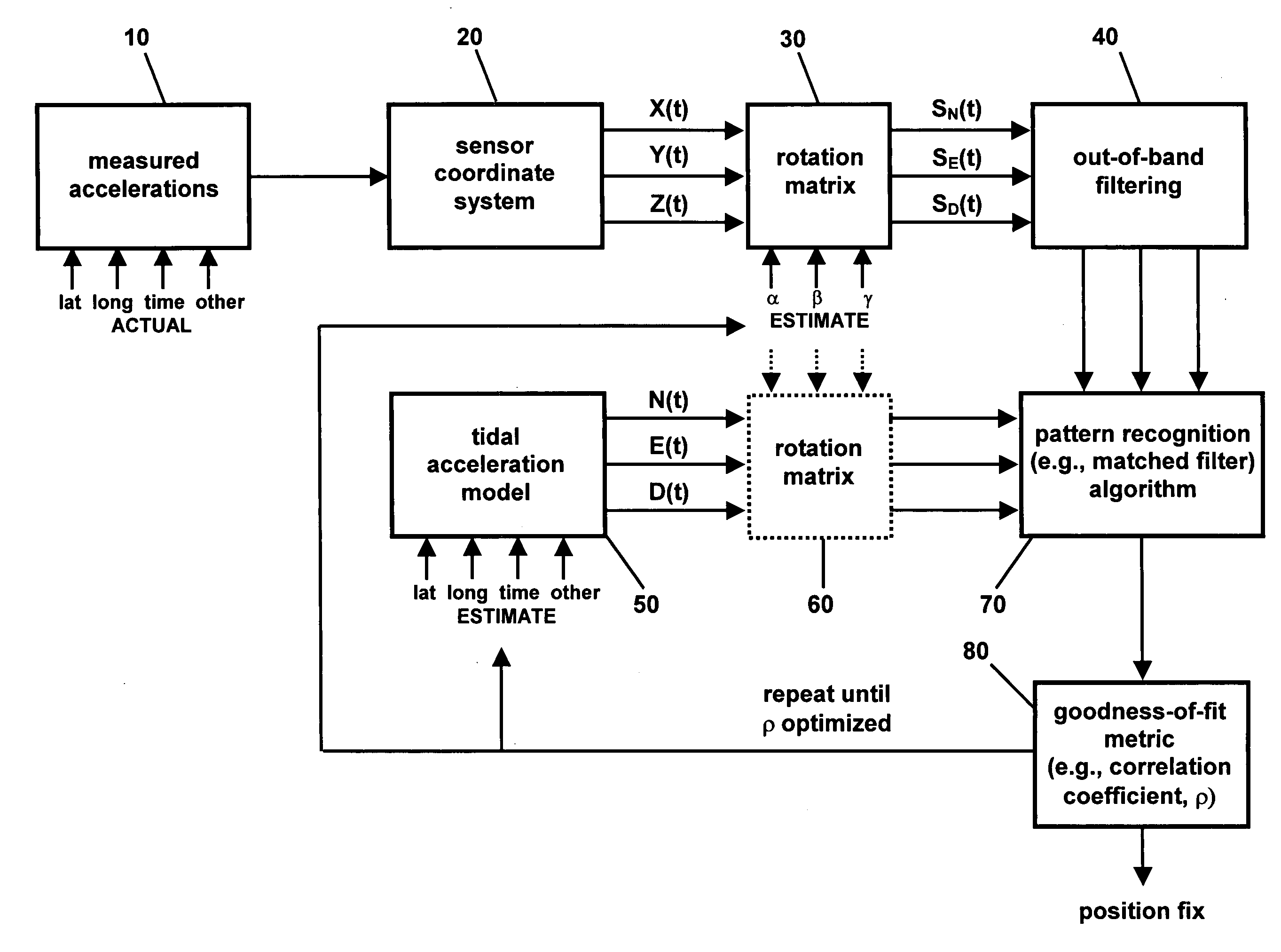
[0022]The present invention comprises a geophysics-based method for determining the position of a stationary earth object using the periodic changes in the gravity vector of the earth caused by the sun- and moon-orbits. Because the local gravity field is highly irregular over a global scale, a model of local tidal accelerations can be compared to actual accelerometer measurements to determine the latitude and longitude of the stationary earth object.

Tidal Acceleration Model

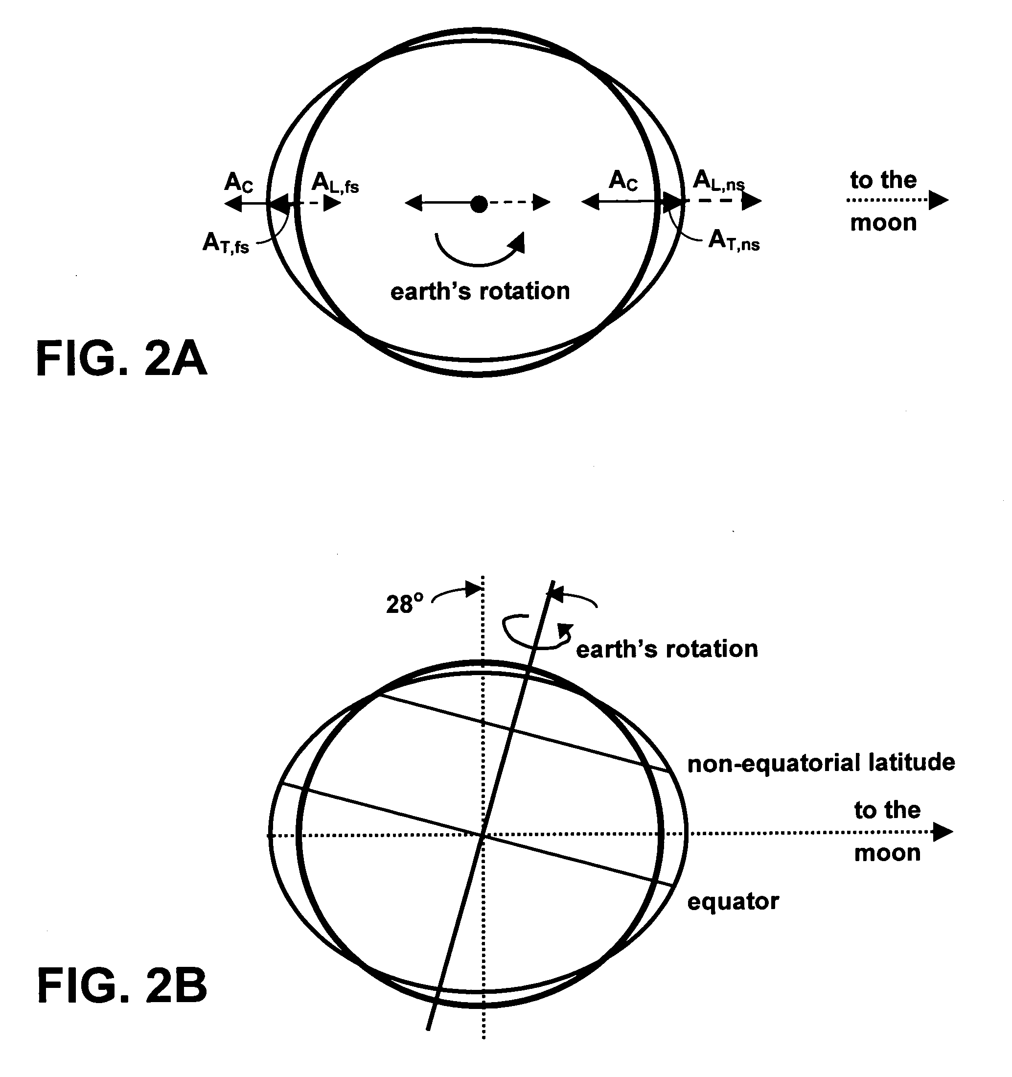
[0023]The earth, sun, and the moon are coupled together by gravitational attraction. For example, the mutual gravitational attraction of the earth and the moon results in the rotation of the earth and the moon about the center of mass of the pair. The common center of mass is located about 1700 km below the earth's surface. This attraction produces an acceleration that acts in the direction of the vector connecting the center of mass of the earth and the moon. Likewise, the mutual gravitational attraction of the e...


PUM


Abstract

A geophysics-based method for determining the position of a stationary earth object uses the periodic changes in the gravity vector of the earth caused by the sun- and moon-orbits. Because the local gravity field is highly irregular over a global scale, a model of local tidal accelerations can be compared to actual accelerometer measurements to determine the latitude and longitude of the stationary object.

Description

STATEMENT OF GOVERNMENT INTEREST[0001]This invention was made with Government support under contract no. DE-AC04-94AL85000 awarded by the U.S. Department of Energy to Sandia Corporation. The Government has certain rights in the invention.FIELD OF THE INVENTION[0002]The present invention relates to geolocation and, in particular, to a geophysics-based method of determining the latitude and longitude of a stationary earth object using the gravity vectors of the earth, sun, and moon.BACKGROUND OF THE INVENTION[0003]Historical forms of navigation include pilotage, dead reckoning, celestial navigation, radio navigation, and inertial navigation. Radio navigation relies on radio-frequency sources with known locations, such as Global Positioning System (GPS) satellites or terrestrial airport beacons, to determine where one is relative to where one wants to go. Inertial navigation systems rely on knowing one's initial position, velocity, and attitude and measuring attitude rates and accelera...

Claims


Application Information

Patent Timeline
Patent Type & Authority Patents(United States)
IPC IPC(8): G01C21/26H04B7/185G01S19/19
CPCG01C21/00G01C21/04
Inventor DAILY, MICHAEL R.ROHDE, STEVEN B.NOVAK, JAMES L.
Owner NAT TECH & ENG SOLUTIONS OF SANDIA LLC
Why Eureka
Try Eureka