Developing apparatus and image forming equipment and method thereof

a technology of image forming equipment and development apparatus, which is applied in the direction of electrographic process equipment, instruments, optics, etc., can solve the problem of contaminating the interior of the image forming equipmen

Active Publication Date: 2005-05-05
HEWLETT PACKARD DEV CO LP
View PDF4 Cites 36 Cited by
  • Summary
  • Abstract
  • Description
  • Claims
  • Application Information

AI Technical Summary

Benefits of technology

[0012] Therefore, the present invention has been developed to overcome the above mentioned problems in the prior art and it is an object of the present invention to provide a developing apparatus and an image forming equipment and method, capable of inhibiting a developer from being scattered.

Problems solved by technology

Further, some toner particles are scattered to an interior of the image forming equipment, thus contaminating the interior of the image forming equipment.

Method used


Image

  • Developing apparatus and image forming equipment and method thereof
  • Developing apparatus and image forming equipment and method thereof
  • Developing apparatus and image forming equipment and method thereof

Examples


first embodiment

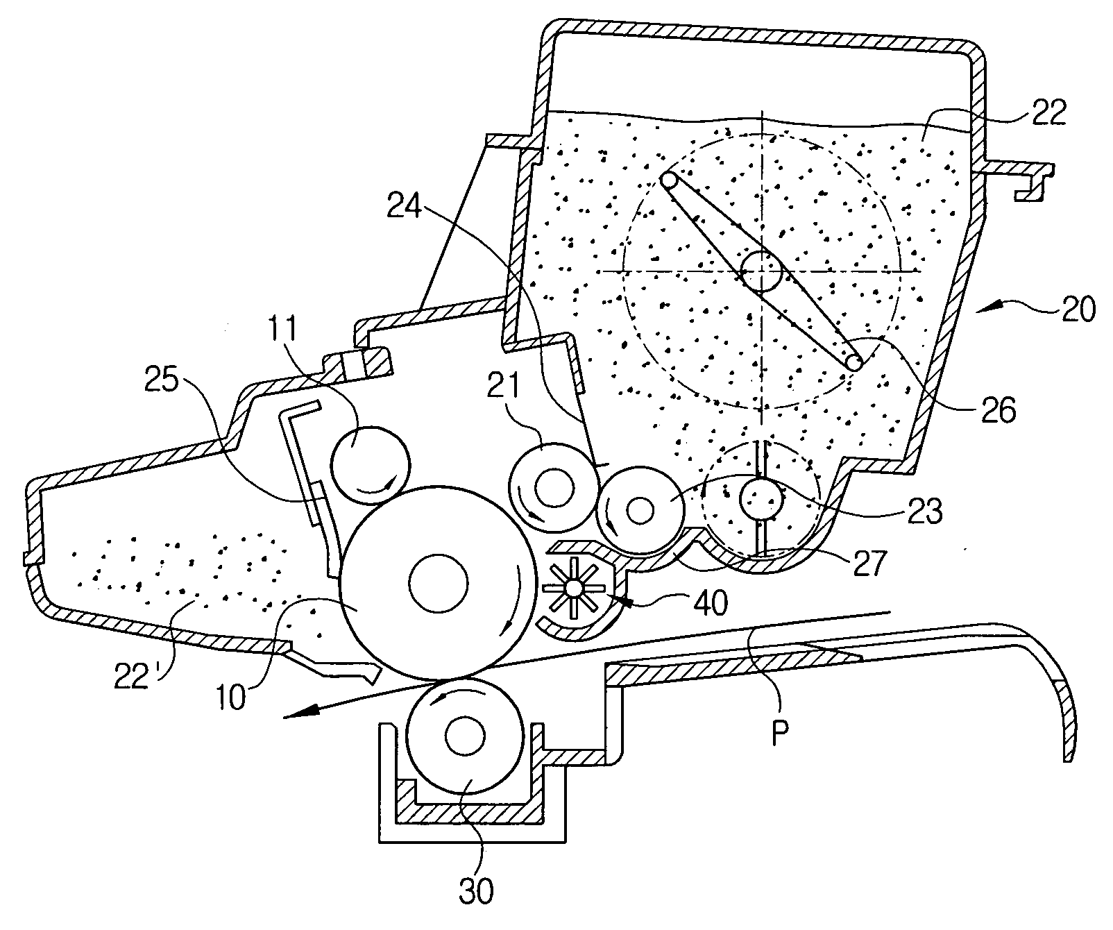
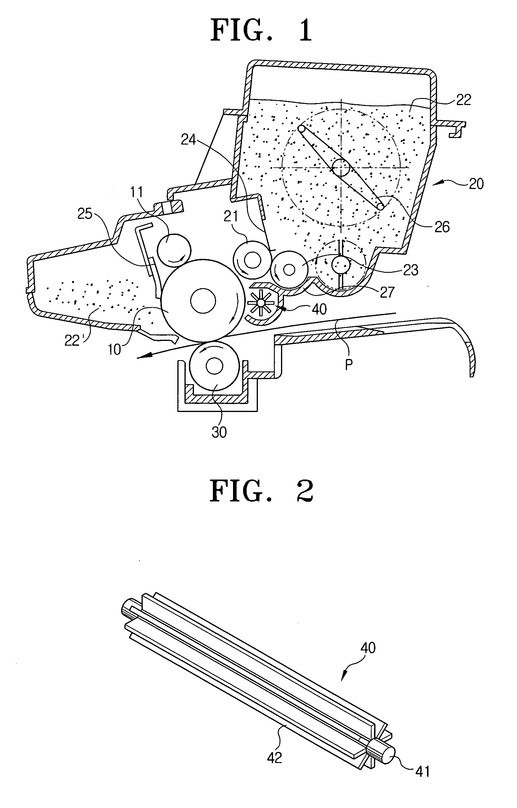
[0061]FIG. 1 illustrates a schematic configuration of an image forming equipment according to the present invention.

[0062] Referring to FIG. 1, the image forming equipment comprises an image carrier 10, a means 11 for charging the image carrier 10 to a predetermined potential, an exposure apparatus (not shown) for scanning light onto the charged image carrier 10 to form an electrostatic latent image in a predetermined shape, a developing apparatus 20 for developing the electrostatic latent image into a toner image, and a transferring unit 30 for transferring the toner image formed on the image carrier 10 to a printing medium P.

[0063] The developing apparatus 20 includes a developer carrier 21 for developing the electrostatic latent image formed on the image carrier 10 while rotating a certain distance from the image carrier 10; a supplying roller 23 for supplying the developer carrier 21 with a developer 22 while rotating in the same direction as the developer carrier 21; a regulat...

second embodiment

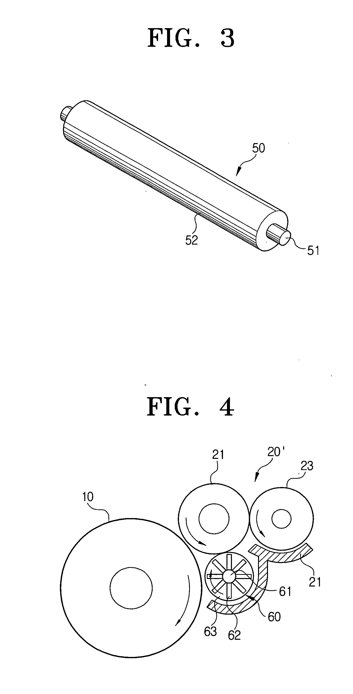
[0083]FIG. 4 schematically shows a main part of an image forming equipment according to the present invention. FIG. 5 is a front view of the developer carrier and the rotational member shown in FIG. 4, and FIG. 6 is a perspective view of the rotational member shown in FIG. 4.

[0084] Referring to FIGS. 4 to 6, a developing apparatus 20′ according to the second embodiment includes a rotational member 60 mounted on the lower portion of the developer carrier 21 and spaced apart from the image carrier 10 at a constant interval.

[0085] As shown in FIG. 6, the rotational member 60 includes a rotational shaft 61, both ends of which are mounted to the housing 27 of the developing apparatus 20′, at least one rotational blade 62 provided around the rotational shaft 61, and a pair of rotational plates 63 provided on both ends of the rotational shaft 61. Here, the rotational blades 62 may be varied in shape or number according to conditions used.

[0086] The pair of rotational plates 63 serve as m...

third embodiment

[0087]FIG. 7 illustrates an image forming equipment according to the present invention.

[0088] Referring to FIG. 7, the image forming equipment according to the third embodiment of the present invention comprises a developing apparatus 72 provided in a main body 71 of the image forming equipment, a paper feeder 73 for feeding the printing medium P to the developing apparatus 72, a laser scanning unit 74, a fixing unit 75, and a transferring unit 76.

[0089] Here, the laser scanning unit 74 scans light to form an electrostatic latent image corresponding to a desired image onto an image carrier 122 provided to the developing apparatus 72.

[0090] The laser scanning unit 74 affixes images onto the printing medium P passing through the developing apparatus 72 under high temperature and pressure, and affixes an image transferred to the printing medium P. Since the laser scanning unit 74 and the fixing unit 75 are conventional, their detailed description will be omitted.

[0091] The developin...


PUM


Abstract

A method and developing apparatus are provided. The method and apparatus comprise a developing carrier, spaced apart from an image carrier at a predetermined interval, for developing an electrostatic latent image formed on the image carrier during rotation; and a rotational member, rotatably installed adjacent to the image carrier, for generating an air stream reverse to that generated by rotation of both the image carrier and the developer carrier, thereby inhibiting a developer from being scattered.

Description

CROSS-REFERENCE TO RELATED APPLICATIONS [0001] This application claims benefit under 35 U.S.C. § 119 from Korean Patent Application Nos. 2004-33575, 2004-51924 & 2003-76212, filed on May 12, 2004, Jul. 5, 2004 & Oct. 30, 2003, respectively, the entire contents of which are incorporated herein by reference. BACKGROUND OF THE INVENTION [0002] 1. Field of the Invention [0003] The invention relates to a developing apparatus and image forming equipment and method thereof. More particularly, the present invention relates to a developing apparatus and image forming equipment and method for preventing a developing agent from contaminating the image forming apparatus. [0004] 2. Description of the Related Art [0005] Image forming equipment such as a laser printer, a light emitting diode (LED) printer, a digital copier, a facsimile for general paper, and so on, have a function of transferring an image signal based on an input digital signal to a printing medium, such as a sheet of paper, in a ...

Claims


Application Information

Patent Timeline
Patent Type & Authority Applications(United States)
IPC IPC(8): G03G15/08
CPCG03G15/0898
Inventor LEE, HYUN-CHEOLKIM, JEONG-SEONKRASNOSLOBODTSEV, VALERIJEON, IN-CHEOL
Owner HEWLETT PACKARD DEV CO LP
Why Eureka
Try Eureka