Light bulb socket for motor vehicle lamps

Inactive Publication Date: 2005-05-05
BERNHARD JURGENHAKE FUR KABELKONFEKTION & METALLVERARBEITUNG MBH
View PDF4 Cites 1 Cited by
  • Summary
  • Abstract
  • Description
  • Claims
  • Application Information

AI Technical Summary

Benefits of technology

[0006] Such an arrangement of the socket body provides, in addition to an easier mounting of contact springs in their supporting partition, the plate, but also an easier contact bonding, or coupling, between the contact springs and power-supply cables, because this bonding can be accomplished outside the cylindrically-shaped part of the socket part. All of these improvements make possible, above all, an automation of the assembly of the socket body with contact springs and the contact coupling, or bonding, between the contact springs and the power-supply cables.
[0007] In a preferred embodiment of the invention, the contact-supporting plate is placed deeply in the cylindrically-formed part of the socket body to be substantially spaced from a rear end edge thereof. In this manner a protective collar-shaped rim portion is created for protecting the contact bonds between the contact springs and the power-supply cables against bumps, and therefore against power breaks.
[0008] A further benefit is provided by the power-supply cables extending perpendicular to a length-wise axis of the socket body, and by their bonding, or coupling, to the contact springs being accomplished by insulation-displacement clamp connection, IDC, technology. Such a contact bonding provides a surer power-supply coupling and can be accomplished quickly and easily.
[0010] A further beneficial embodiment of the invention is achieved by the contact springs having U-shaped forms in cross section in areas at which they are held by the plate and in areas at which the insulation-displacement, IDC, slits for the bonds with the power-supply cables are arranged. In this manner, for one thing, securer seatings for the contact springs are formed in the plate and, for another thing, insulation-displacement connections, per power-supply cable and contact spring, are doubled, which is beneficial for secure establishment of good power-supply connections and mechanical strength of the bonds.
[0011] Mechanical strength as well as reduction of movement play between the contact springs and their supporting plate is improved by providing the plate with block-shaped protrusions extending toward a socket-rear end in which grooves are formed for receiving leg edges of the cross-sectional-U-shaped contact spring portions.
[0012] For further increasing contact reliability between contact springs and power-supply cables and for a water-proof closing of the rear end of the bulb socket, a bowel space defined by the plate and a rear end portion of the cylindrical portion of the socket body is filled with a bonding agent.

Problems solved by technology

Such a structure indeed has the generally well-known advantages of one-piece construction, however it has the disadvantage that contact springs can only be shoved with difficulty and laboriously into the transverse partition that is arranged deep in the cylindrical body.
Such a mounting of the contact springs, or elements, is difficult and requires a great deal of play between the contact springs and receiving openings in the partition.
A connection between the contact springs and power-supply cables is limited to use of plug connectors because a space in the hull-shaped socket body is normally too small to accomplish an insulation-displacement (or insulation-piercing) clamping connection, IDC, therefor after the contact springs are placed in the partition.

Method used


Image

  • Light bulb socket for motor vehicle lamps
  • Light bulb socket for motor vehicle lamps
  • Light bulb socket for motor vehicle lamps

Examples


Embodiment Construction

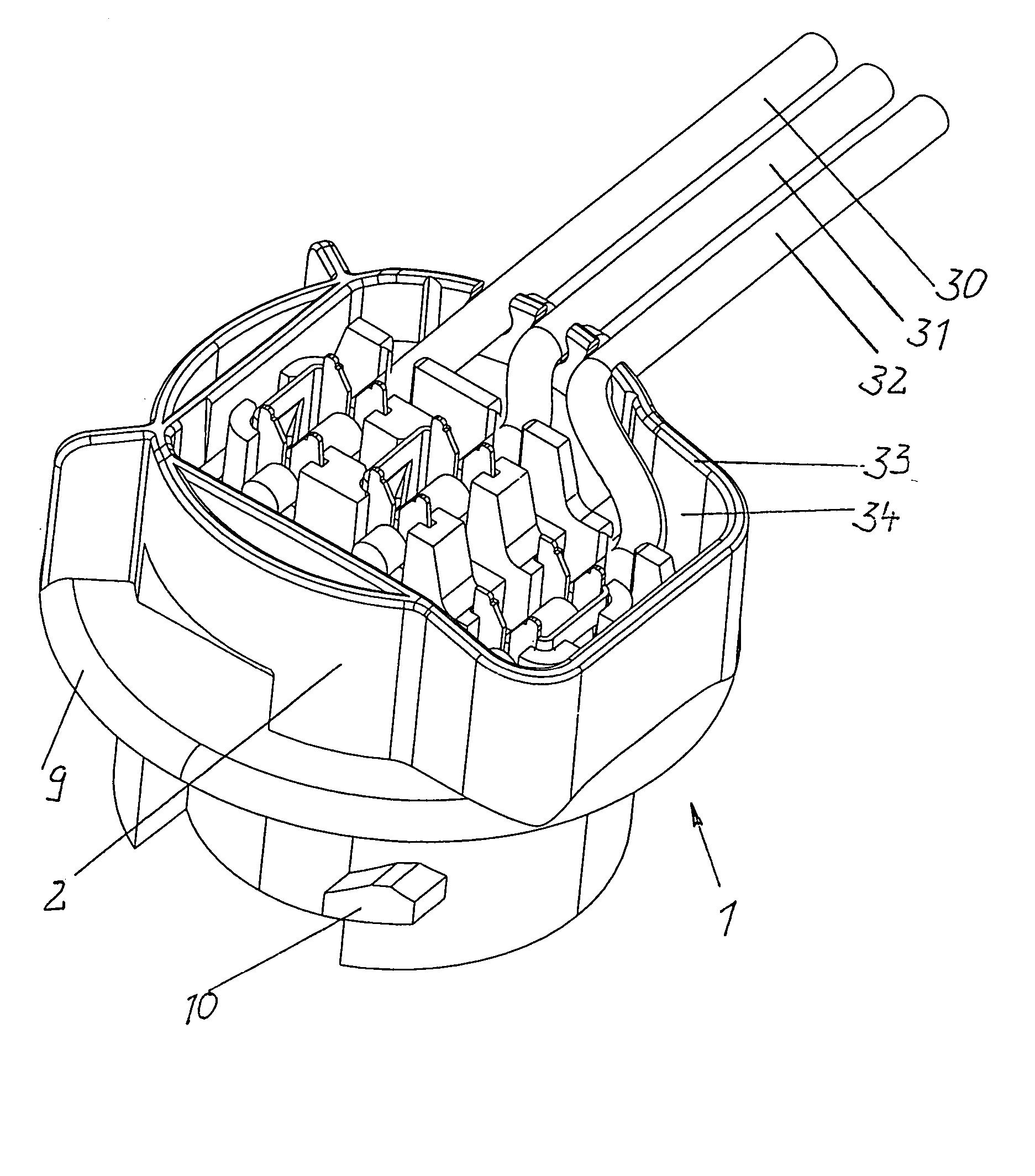
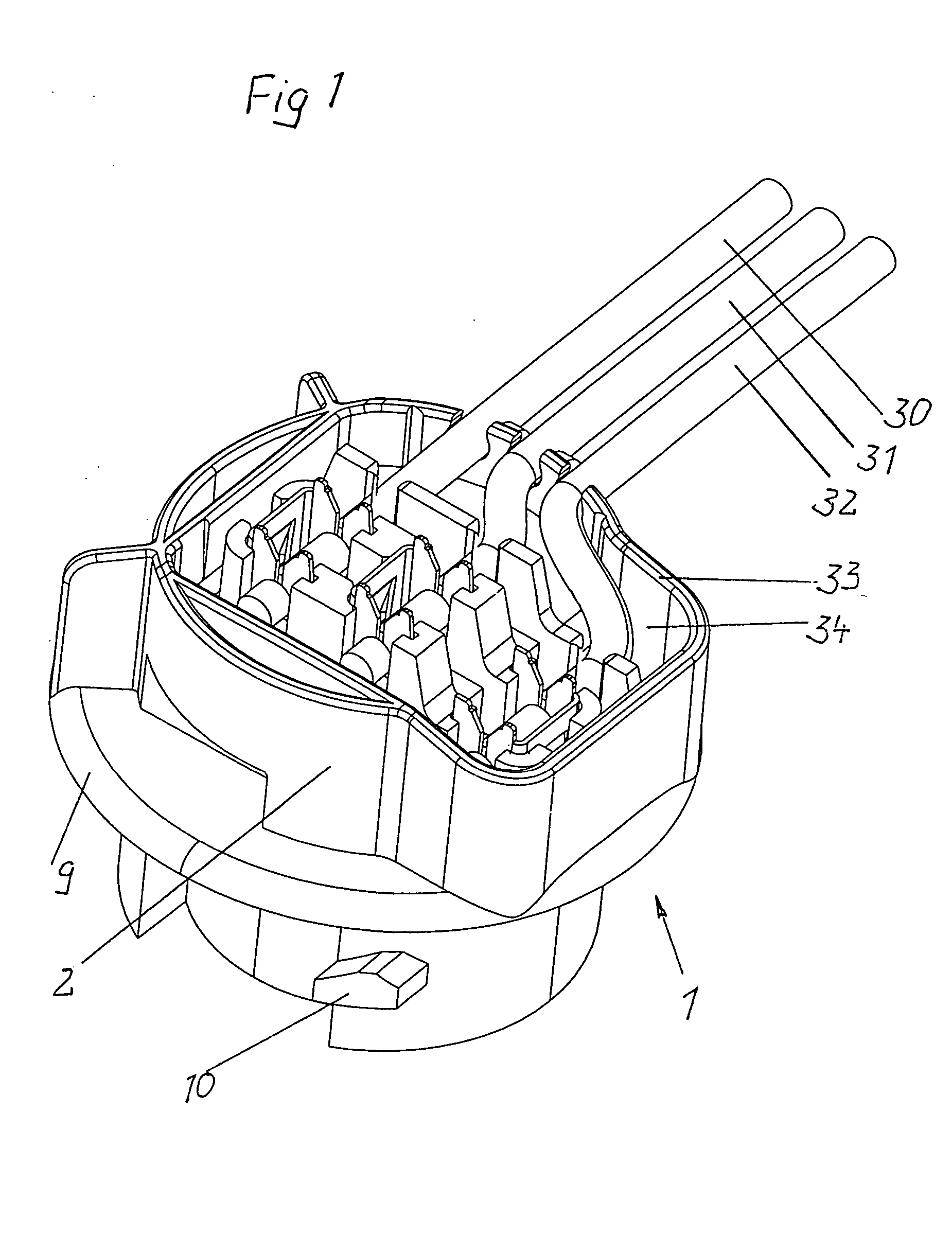
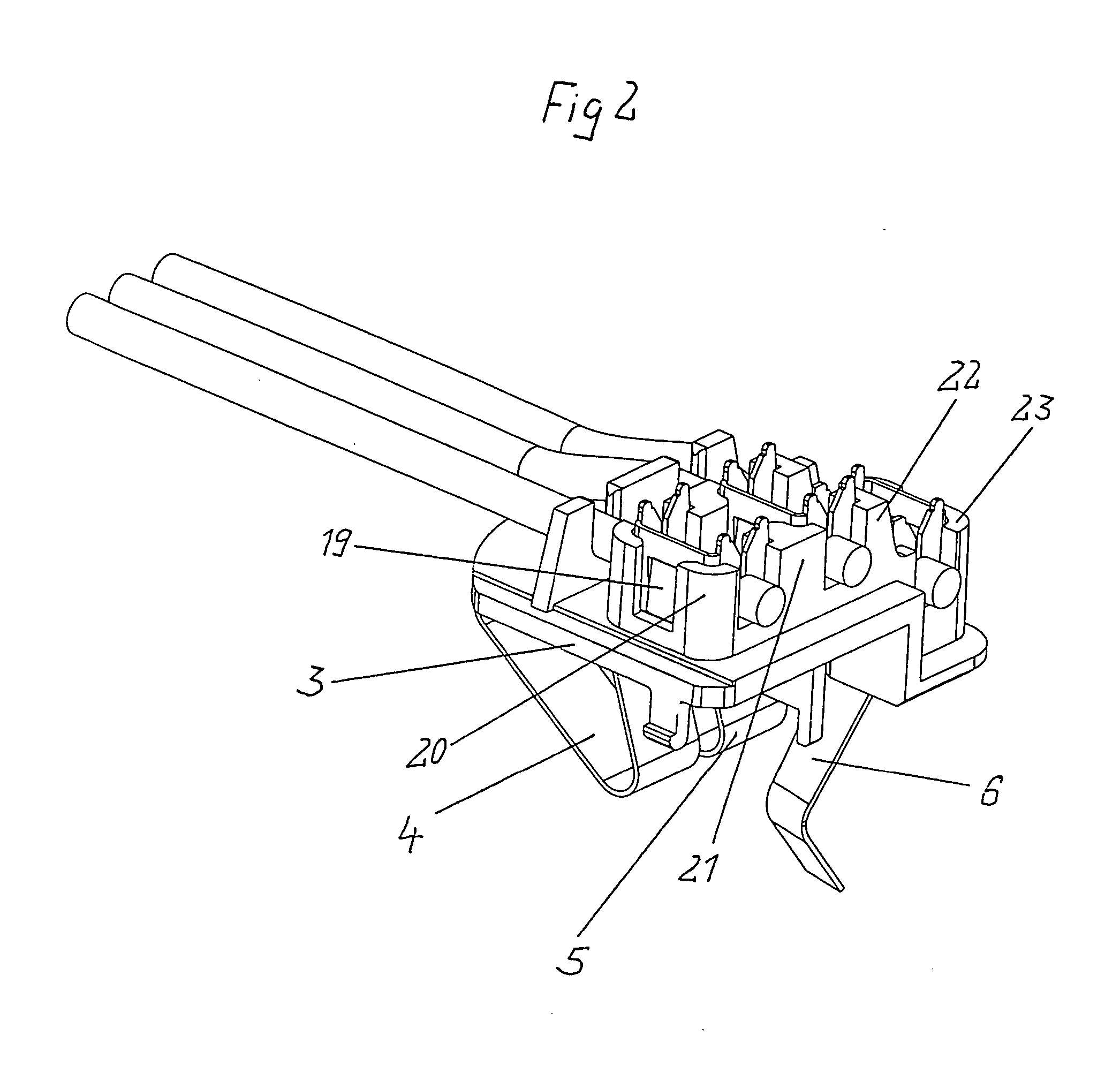
[0018] A bulb socket has a socket body 1, that is formed from a cylindrically-shaped part 2 and a plate 3 supporting contact springs 4, 5 and 6, with the plate 3 being inset deeply in the cylindrically-shaped part 2 from a rear end thereof. In the depicted embodiment, a connection of the plate 3 with the cylindrically-shaped part 2 is achieved by flexibly yielding small arms 7 on the plate 3 whose snap cams 8 automatically index, or snap, into corresponding cavities, or indentations, of the cylindrically-shaped part 2. This connection can also be achieved by welding, adhesive and / or combinations including these.

[0019] An attachment of the socket body 1 in a receiving part, for example in a reflector, is accomplished by a outer flange 9 that is arranged in a middle area of the cylindrically-shaped part 2 and a front, adjacent, radially protruding cam lobe 10 that together form a sliding bayonet catch lock.

[0020] The contact springs 4, 5, 6 are U-shaped in cross section (a section t...


PUM


Abstract

A light bulb socket for a motor vehicle lamp has a hull-shaped socket body formed of a cylindrically-shaped part and a separate plate for receiving contact springs. For stabilizing a seating of the contact springs, the plate has rearwardly directed protrusions that snugly enclose cross-sectional U-shaped end portions of the contact springs. Legs of the U-shaped end portions of the contact springs form a double contact bond to power lead cables with insulation-displacement connections.

Description

BACKGROUND OF THE INVENTION [0001] This application claims a priority based on German Gebrauchsmuster Nr. 203 16 669.8, filed Oct. 30, 2003. [0002] This invention concerns light bulb sockets for holding light bulbs, such as incandescent light bulbs, of motor-vehicle lamps of a type formed of a hull-shaped socket body of resinous plastic having a transverse partition into which contact springs can be shoved from a bulb side for snap-locking engagement. [0003] In known sockets of this type, for example as taught in U.S. Pat. No. 3,800,267 and in Australian patent application 26517 / 77, a contact-spring-receiving, transverse, partition is constructed as one piece with a cylindrical sleeve body. Such a structure indeed has the generally well-known advantages of one-piece construction, however it has the disadvantage that contact springs can only be shoved with difficulty and laboriously into the transverse partition that is arranged deep in the cylindrical body. When bulb-contacting end ...

Claims


Application Information

Patent Timeline
IPC IPC(8): H01R4/24H01R13/24
CPCH01R4/2454H01R2201/26H01R13/2442
Inventor WALLMEIER, WILHLEM FRIEDERICH
Owner BERNHARD JURGENHAKE FUR KABELKONFEKTION & METALLVERARBEITUNG MBH
Why Eureka
Try Eureka