
Noncylindrical stent deployment system for treating vascular bifurcations

a deployment system and vascular bifurcation technology, applied in the field of vascular bifurcation noncylindrical stent deployment system, can solve the problems of unsuitability of conventional stents, unsuitability of vascular narrowing or occlusive treatment, immediate or delayed occlusion,

Inactive Publication Date: 2005-05-05
BIOSENSORS INT GROUP
View PDF99 Cites 502 Cited by
  • Summary
  • Abstract
  • Description
  • Claims
  • Application Information

AI Technical Summary

Benefits of technology

[0017] The releasable restraint may comprise an axially moveable control element extending along the length of the flexible body. The releasable restraint may also comprise a tubular sheath, for restraining the stent. The tubular sheath may be attached to an axially moveable pull wire.
[0018] In accordance with a further aspect of the present invention, there is provided a method of treating a vascular bifurcation of a main vessel into first and second branch vessels. The method comprises the steps of deploying a substantially cylindrical stent in a first branch vessel which is distal to the bifurcation, and deploying a tapered stent in the main vessel, proximal to the bifurcation. The tapered stent tapers in a distal direction from a smaller proximal diameter to a larger distal diameter which faces the bifurcation.
[0019] In accordance with another aspect of the present invention, there is provided a stent deployment catheter. The catheter comprises an elongate flexible tubular body, having a proximal end and a distal end. A noncylindrical, self expandable stent is carried by the distal end. A hand piece is provided on the proximal end. A control is provided on the hand piece, for controllably removing a restraint from the noncylindrical self expandable stent. In one application, the control has a first position for indicating a partial deployment of the stent, and a second position indicating complete deployment of the stent.

Problems solved by technology

A conventional stent is not entirely suitable for the treatment of a narrowing situated in the area of a bifurcation, since its engagement both in the principal conduit and in one of the secondary conduits can cause immediate or delayed occlusion of the other secondary conduit.
This equipment permits reinforcement of the bifurcation but appears unsuitable for treating a vascular narrowing or an occlusive lesion, in view of its structure and of the low possibility of radial expansion of its two constituent elements.
Thus, this equipment does not make it possible to fully support this wall or to treat a dissection in the area of this wall.
Additionally, the separate positioning of these two elements is quite difficult.

Method used


Image

  • Noncylindrical stent deployment system for treating vascular bifurcations
  • Noncylindrical stent deployment system for treating vascular bifurcations
  • Noncylindrical stent deployment system for treating vascular bifurcations

Examples


Embodiment Construction

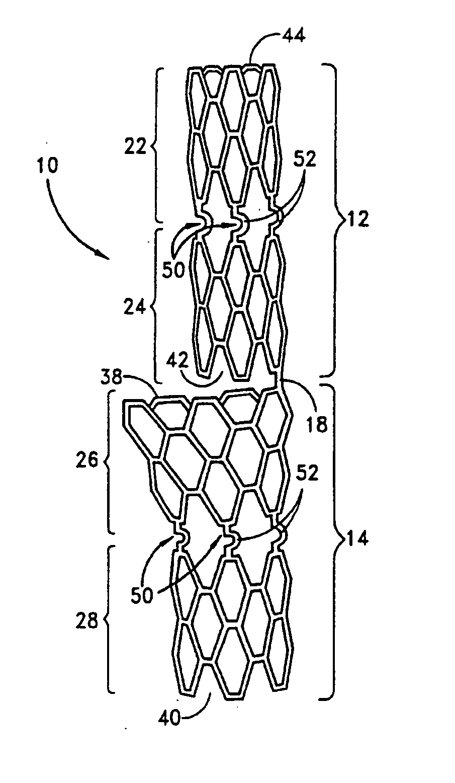
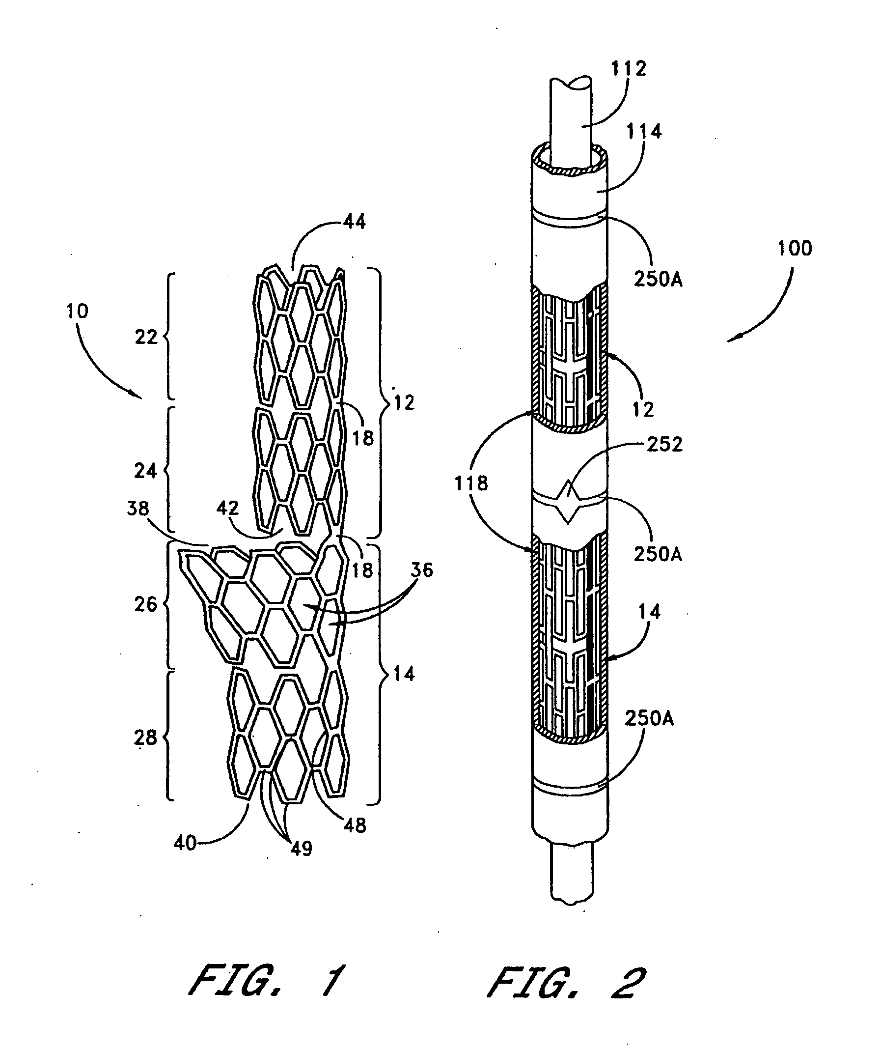
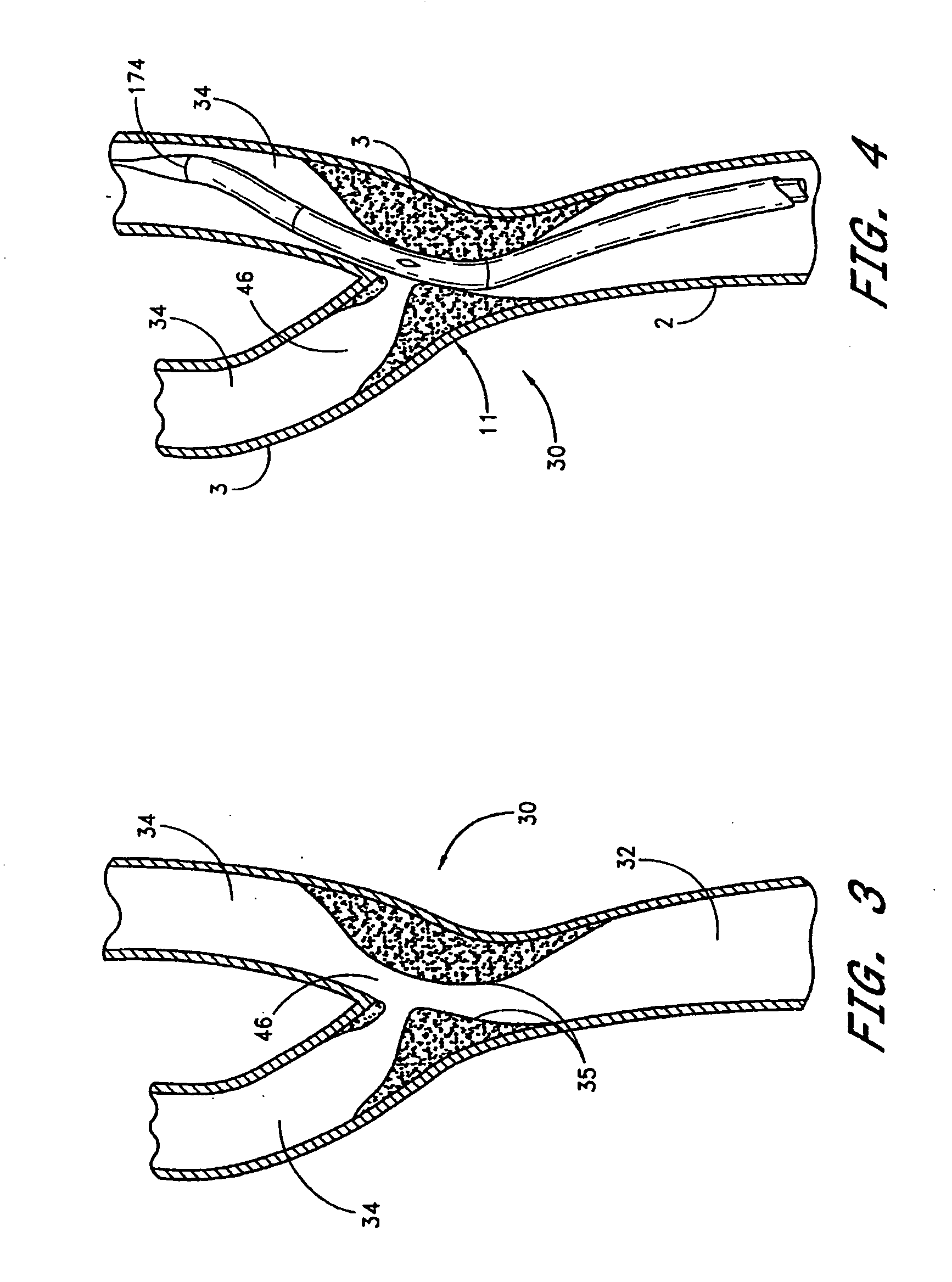
[0051] As described above, the attached Figures illustrate a stent system and corresponding delivery system for use in treating vessels (e.g. conduits) within the human body at areas of bifurcations. FIG. 3 shows a bifurcation 30 in which a main conduit or vessel 32 separates into two secondary branch conduits or vessels 34. The stent system generally includes a pair of dissimilar stents specifically designed for use in an area of a bifurcation 30. Such dissimilar stents are then disposed on an elongate catheter for insertion into the human body. The dissimilar stents may be self-expanding or manually expandable such as by a balloon about which the stents may be disposed as will be described in further detail below.

[0052]FIG. 1 shows one embodiment of an expandable stent system 10 permitting the treatment of bodily conduits in the area of a bifurcation such as that shown. The stent system 10, shown in an expanded state in FIG. 1, generally comprises first 12 and second 14 stent por...


PUM

PropertyMeasurementUnit
distanceaaaaaaaaaa
distanceaaaaaaaaaa
lengthaaaaaaaaaa

Abstract

A device and method for treating pathological narrowing of fluid-carrying conduits of the human body (such as blood vessels) in an area of a bifurcation is disclosed. In particular, a stent system carries a self expandable noncylindrical stent, which is particularly suited for treating a widened portion of a blood vessel immediately proximal to a bifurcation. A stent delivery system is also disclosed, for delivering the stent such that a larger expanded diameter end of the stent faces the bifurcation, and a smaller expanded diameter end of the stent faces proximally in the main vessel.

Description

[0001] This is a Divisional of U.S. patent application Ser. No. 10 / 282,957 filed on Oct. 28, 2002 which is a Continuation of U.S. patent application Ser. No. 10 / 225,484 filed on Aug. 20, 2002 which is a Continuation-In-Part of U.S. patent application Ser. No. 09 / 580,597, which was filed on May 30, 2000, the disclosures of which are incorporated in their entirety herein by reference.BACKGROUND [0002] 1. Scope of the Invention [0003] The present invention relates to an apparatus permitting the treatment of bodily conduits, typically blood vessels, in an area of a bifurcation, e.g. in an area where a principal conduit separates into two secondary conduits. It also relates to equipment for positioning this apparatus. [0004] 2. Description of the Related Art [0005] It is known to treat narrowing of a rectilinear blood vessel by means of a radially expandable tubular device, commonly referred to as a stent. This stent is introduced in the unexpanded state into the internal lumen of the ve...

Claims


Application Information

Patent Timeline
Patent Type & Authority Applications(United States)
IPC IPC(8): A61L27/00A61F2/06A61M25/00A61M25/01
CPCA61F2/856A61F2/91A61F2/915A61F2/954A61F2/958A61F2220/0058A61F2002/067A61F2002/91541A61F2002/9517A61F2002/9583A61F2/966A61F2/9517A61F2/9661
Inventor SEQUIN, JACQUESELICKER, ROBERT JOHNLABORDE, JEAN-CLAUDE
Owner BIOSENSORS INT GROUP
Learn More