

Cache control method in a storage system with multiple disk controllers
a storage system and controller technology, applied in the direction of instruments, input/output to record carriers, redundancy hardware error correction, etc., can solve the problems of data loss that poses a serious reliability problem, data loss that exerts a serious influence on operations, and not-yet-written data cannot be restored, etc., to achieve high reliability and high-speed data access
- Summary
- Abstract
- Description
- Claims
- Application Information
AI Technical Summary
Benefits of technology
Problems solved by technology
Method used
Image


Examples
first embodiment
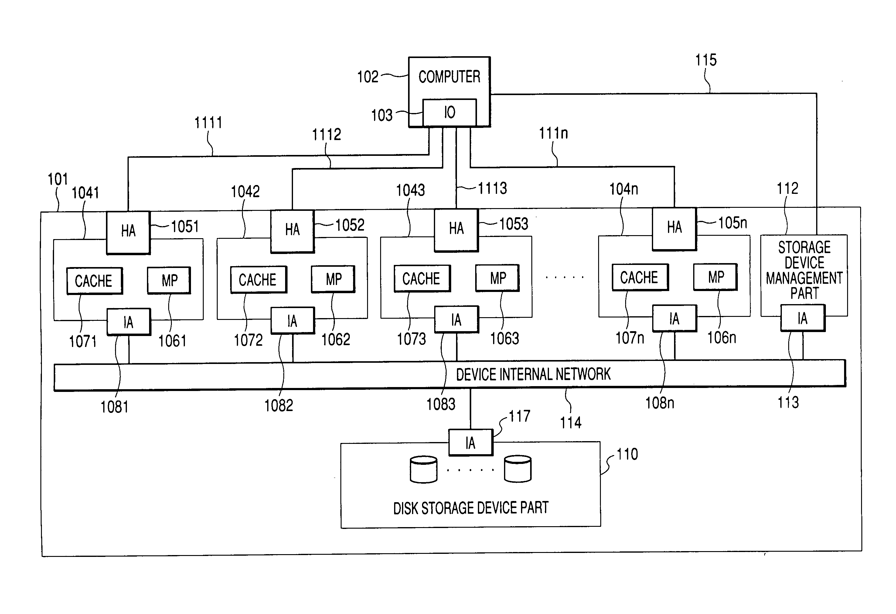
[0034]FIG. 1 is a block diagram showing the configuration of a storage device of the present invention.
[0035] In FIG. 1, a storage device 101 to which the present invention is applied is connected to a computer 102 that accesses data of the storage device 101. The storage device 101 is provided with a disk storage device part 110 for storing data.
[0036] The storage device 101, like the conventional storage device (FIG. 9), is provided with n disk controllers 1041, 1042, 1043 . . . 104n (n>2, where n is an integer) that control data access between the computer 102 and the disk storage device part 110. The disk controllers 1041 to 104n include cache memories 1071, 1072, 1073 . . . 107n and microprocessors (MP) 1061, 1062, 1063, . . . , 106n, respectively. The cache memories 1071 to 107n are semiconductor memories that, to speed up data access, temporarily store data to be written to the disk storage device part 110 and data read from the disk storage device part 110.
[0037] The micro...
second embodiment
[0077]FIG. 6 is a block diagram showing the configuration of a storage device of the present invention.
[0078] A storage device 601 of FIG. 6, which has the same configuration as the storage device 101 shown in FIG. 1, is different from it in a method of data communication between the storage device 601 and a computer 602. The storage device 601 is provided with a disk storage device part 610 for storing data. Disk controllers 6041, 6042, 6043, . . . , and 604n (n>2, where n is an integer) include at least cache memories 6071, 6072, 6073, . . . , and 607n, and microprocessors (MP) 6061, 6062, 6063, . . . , and 606n, respectively.
[0079] Between the computer 602 and the disk controllers 6041 to 604n, data is transmitted and received using a protocol such as, e.g., fiber channel through a network switch 616 disposed between an interface card (IO) 603 within the computer and host adapter cards (HA) 6051, 6052, 6053, . . . , and 605n within the disk controllers. Connection is made by opt...
third embodiment
[0083]FIG. 7 is a block diagram showing the configuration of a storage device of the present invention.
[0084] A storage device 701 shown in FIG. 7 is different from the storage device 101 of the first embodiment shown in FIG. 1, in that, instead of the computer 102, m (m>0, where m is an integer) computers 7181, 7182, . . . , and 718m are included within the storage device 701. The storage device 701 is provided with a disk storage device part 710 for storing data. Disk controllers 7041, 7042, 7043, . . . , and 704n (n>2, where n is an integer) include at least cache memories 7071, 7072, 7073, . . . , and 707n, and microprocessors 7061, 7062, 7063, . . . , and 706n, respectively.
[0085] The computers 7181 to 718m and the disk controllers 7041 to 704n are connected with each other using a device internal network 714 such as, e.g., InfiniBand through interface adaptors (IA) 7081, 7082, 7083, . . . , 708n, 7191, 7192, . . . , and 719m so that data is transmitted and received between th...
PUM
 Abstract
Description
Claims
Application Information