Shadow-free shutter arrangement and method

a technology of shutter arrangement and shadow-free shutter, which is applied in the direction of muffler furnaces, lighting and heating apparatus, furnaces, etc., can solve the problems of excessive dopant diffusion, non-uniform heating of the wafer surface, and undesirable effects of annealing the device side of a semiconductor wafer in the absence of precision control

Active Publication Date: 2005-05-12
MATTSON TECHNOLOGY +1
View PDF1 Cites 46 Cited by
  • Summary
  • Abstract
  • Description
  • Claims
  • Application Information

AI Technical Summary

Benefits of technology

[0015] In a continuing aspect of the present invention, a system and method are described for processing a workpiece by applying controlled heat thereto. The system includes an apparatus having a heating arrangement for use in a confronting relationship with a treatment width of the workpiece to subject the workpiece to a direct radiation that is produced by the heating arrangement. A radiation shield is supported for movement between (i) a retracted state to allow the direct radiation to reach the workpiece without producing shadowing thereon, and (ii) an extended state in which the radiation shield serves to at least partially block at least a portion of the direct radiation from reaching the workpiece such that the radiation shield moves a distance between the retracted state and the extended state which is less than the treatment width.
[0016] In another aspect of the present invention, as part of a system for processing a workpiece, having a treatment width, by applying controlled heat thereto, an apparatus and method are described including a heating arrangement for use in a confronting relationship with the treatment width of the workpiece to subject the workpiece to a direct radiation that is produced by the heating arrangement. A radiation shield, including a plurality of members, is supported for movement between (i) a retracted state to allow the direct radiation to reach the workpiece without producing shadowing thereon, and (ii) an extended state in which the radiation shield serves to at least partially block at least a portion of the direct radiation from reaching the workpiece such that each of the members moves a distance between the open state and the extended state which is less than the treatment width.

Problems solved by technology

Unfortunately, annealing the device side of a semiconductor wafer can produce undesirable effects in the absence of precision control.
As is recognized by Pas, the described configuration is problematic since the interposition of the shutter system, between the wafer and heating elements, produces shadowing on the wafer with the shutters in their open position.
The result of such shadowing is non-uniform heating of the wafer surface.
Increasing exposure time in order to properly heat treat the shadowed areas is likely to produce excessive dopant diffusion problems in areas of a wafer that are directly exposed to the heaters.
While the arrangement of Pan does not exhibit the shadowing problem of the shutter arrangement of Pas, it is submitted that another important problem would be introduced in any attempt to use this configuration in the context of Pas, or generally as part of a rapid thermal process, as will be discussed immediately hereinafter.
Still referring to FIG. 2, implementation of a heating profile that is controlled, at least in part, using medium 40 would be problematic for a particular reason.
If actual processing were underway, with the lamps emitting radiation, the wafer would be highly non-symmetrically exposed to radiation, resulting in unpredictable and unacceptable consequences insofar as RTP contemplated by the present invention.

Method used


Image

  • Shadow-free shutter arrangement and method
  • Shadow-free shutter arrangement and method
  • Shadow-free shutter arrangement and method

Examples


Embodiment Construction

[0050] The following description is presented to enable one of ordinary skill in the art to make and use the invention and is provided in the context of a patent application and its requirements. Various modifications to the described embodiments will be readily apparent to those skilled in the art and the generic principles herein may be applied to other embodiments. Thus, the present invention is not intended to be limited to the embodiment shown but is to be accorded the widest scope consistent with the principles and features described herein.

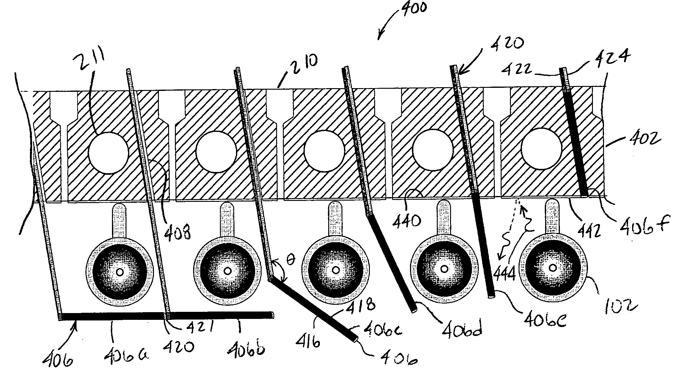
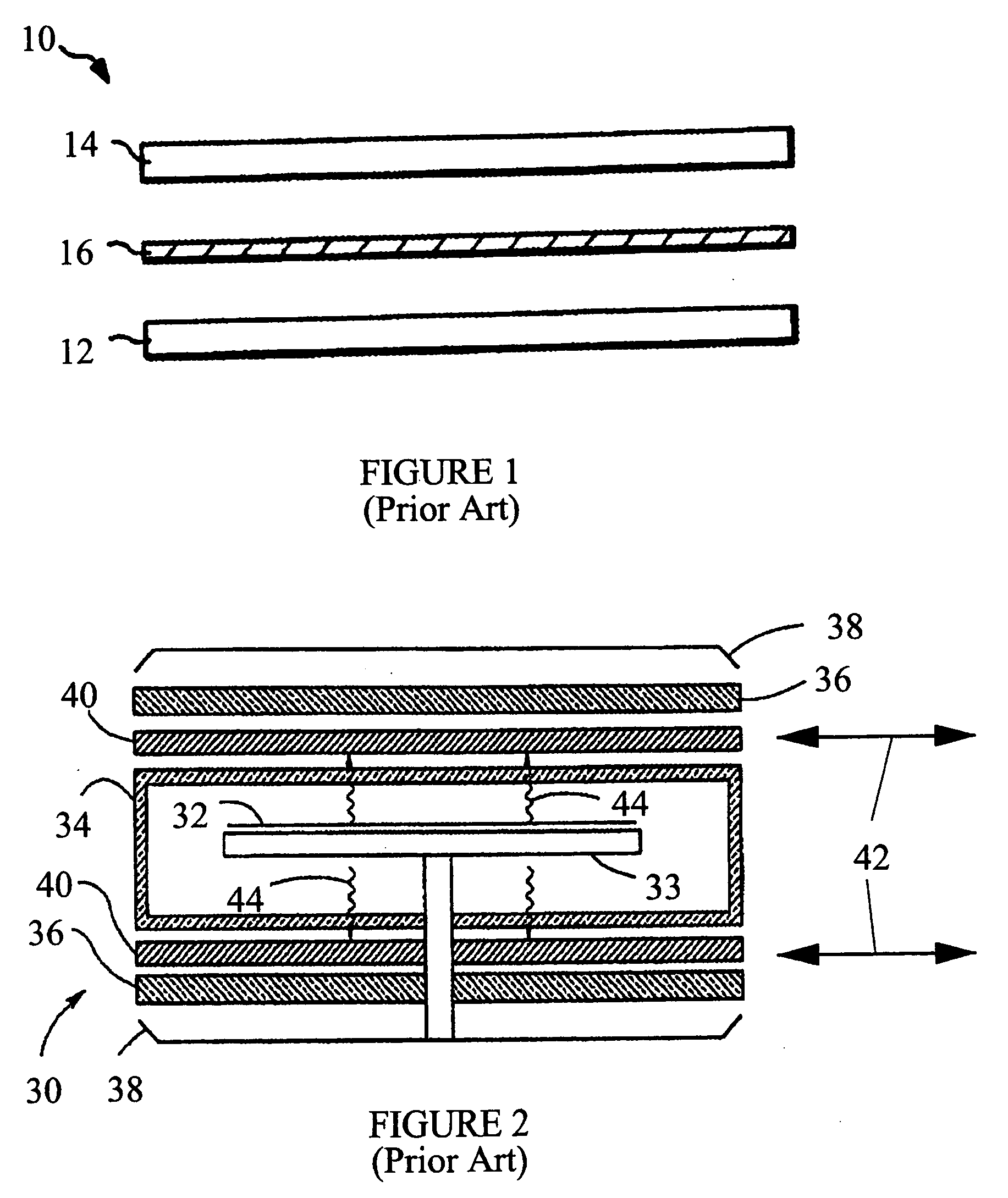
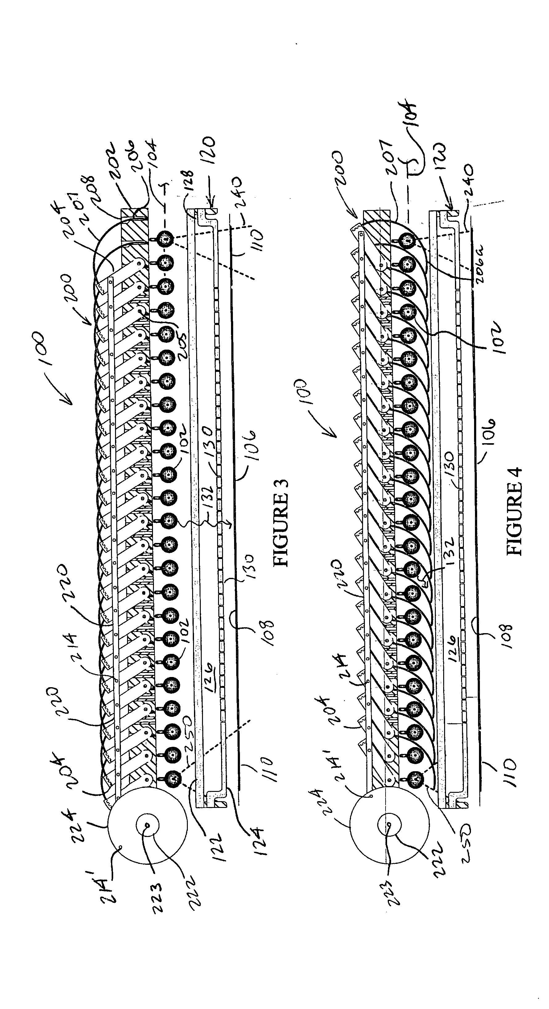
[0051] Having previously described FIGS. 1 and 2, attention is immediately directed to FIG. 3 which is a diagrammatic elevational view of an RTP treatment system, produced in accordance with the present invention, and generally indicated by the reference numeral 100. It is noted that like reference numbers are used to refer to like components throughout the various figures and that the figures are not drawn to scale in order to enhance the...


PUM

PropertyMeasurementUnit
diameteraaaaaaaaaa
diameteraaaaaaaaaa
lengthaaaaaaaaaa

Abstract

As part of a system for processing a workpiece by applying a controlled heat to the workpiece, a heating arrangement includes an array of spaced apart heating elements for use in a confronting relationship with the workpiece to subject the workpiece to a direct radiation that is produced. A radiation shield includes a plurality of members supported for movement between (i) retracted positions, which allow the direct radiation to reach the workpiece, and (ii) extended positions, in which the plurality of members cooperate in way which serves to at least partially block the direct radiation from reaching the workpiece and to absorb radiation emitted and reflected by the workpiece and thereby achieve greater control of the time-temperature profile than previously obtainable. At least certain ones of the members move between adjacent ones of the heating elements in moving those certain members between the retracted and extended positions. Tubular, curved and plate-like member configurations can be used.

Description

BACKGROUND OF THE INVENTION [0001] The present invention is related generally to the field of Rapid Thermal Processing (RTP) of a workpiece and, more particularly, to a radiation shield including a plurality of segments for use in applying controlled heat to the workpiece. [0002] In the production of devices including, but not limited to semiconductors, optoelectronic devices, flat panel displays and MEMS (Micro Electro-Mechanical Systems), at least some processing steps may require the application of controlled heat. For example, in the instance of semiconductors, certain processing steps require the application of heat to wafers and other such workpieces to accomplish annealing. In particular, ion implantation is often used to introduce a dopant in selected areas of a wafer. An RTP anneal is thereafter applied, since the ion implantation process damages the crystal lattice structure of the exposed, selected areas of the wafer, leaving the implanted dopant atoms in interstitial sit...

Claims


Application Information

Patent Timeline
Patent Type & Authority Applications(United States)
IPC IPC(8): B23HF27B5/14F27B17/00F27D5/00F27D11/00H01L21/00
CPCF27B17/0025H01L21/67115F27D5/0037
Inventor DEVINE, DANIEL J.LEE, YOUNG JAITIMANS, PAUL J.LEMA, FRANK ALLAN
Owner MATTSON TECHNOLOGY
Why Eureka
Try Eureka