Temperature detection device and vehicle air conditioner using the same

a temperature detection device and temperature sensor technology, applied in the direction of ventilation systems, heating types, instruments, etc., can solve the problem that the rear ir sensor cannot stably detect the surface temperature of the passenger on the rear sea

Inactive Publication Date: 2005-05-12
DENSO CORP
View PDF2 Cites 25 Cited by
  • Summary
  • Abstract
  • Description
  • Claims
  • Application Information

AI Technical Summary

Benefits of technology

[0005] In view of the above-described problems, it is an object of the present invention to provide a temperature detection device and a vehicle air conditioner having a non-contact t

Problems solved by technology

However, in this case, the rear IR sensor may not stably detect the surface temperature of the passenger on

Method used


Image

  • Temperature detection device and vehicle air conditioner using the same
  • Temperature detection device and vehicle air conditioner using the same
  • Temperature detection device and vehicle air conditioner using the same

Examples


first embodiment

(First Embodiment)

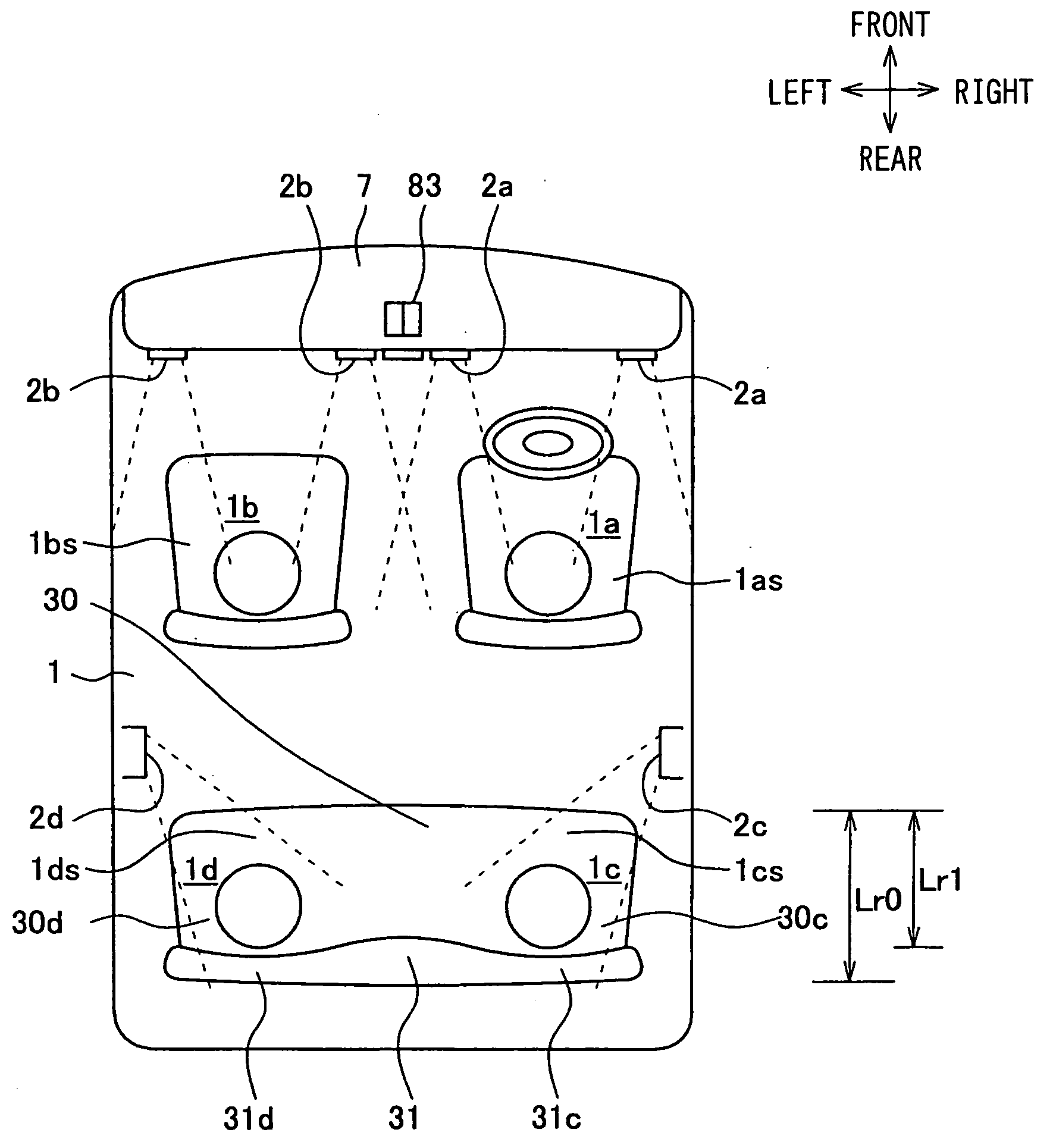
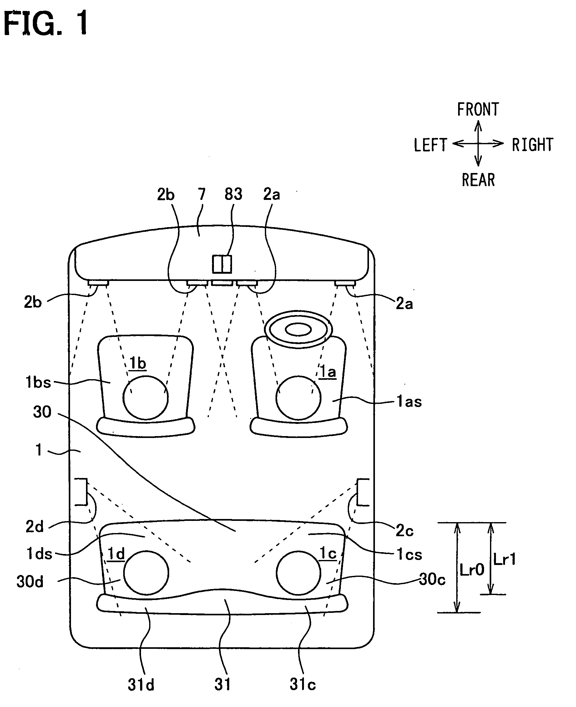
[0050] The first embodiment of the present invention will be now described with reference to FIGS. 1-10. In the first embodiment, the present invention is typically applied to an air conditioner for a vehicle for independently controlling each of air-conditioning operations of air conditioning zones 1a, 1b, 1c, 1d located leftward and rightward on the front seat side and located leftward and rightward on the rear seat side within a vehicle compartment interior 1 (passenger compartment).

[0051]FIG. 1 is a schematic diagram showing the arrangement of the air conditioning zones 1a, 1b, 1c, 1d. The air conditioning zone 1a is located on the right-hand side in the front seat air conditioning zone. The air conditioning zone 1b is located on the left-hand side in the front seat air conditioning zone. The air conditioning zone 1c is located on the right-hand side in the rear seat air conditioning zone. The air conditioning zone 1d is located on the left-hand side in the re...

second embodiment

(Second Embodiment)

[0160] The second embodiment of the present invention of the present invention will be now described with reference to FIGS. 11-13. In the second embodiment, the structure of matrix sensors 70a, 70b that are a non-contact temperature sensor 70 is different from that of the above-described first embodiment.

[0161] As shown in FIG. 11, the non-contact temperature sensor 70 of the second embodiment includes the right matrix IR sensor 70a arranged to face toward the rear right passenger RrDr, and the left matrix IR sensor 70b arranged to face toward the rear left passenger RrPa. The right matrix IR sensor 70a and the left matrix IR sensor 70b are arranged on the ceiling portion adjacent to each other. The matrix IR sensors 70a, 70b are contained in a single package (casing), and the package is arranged at a suitable position in the passenger compartment. Both the matrix IR sensors 70a, 70b have the same structure.

[0162] Infrared rays, radiated from a detecting subjec...

third embodiment

(Third Embodiment)

[0180] The third embodiment of the present invention will be now described with reference to FIGS. 14, 15A and 15B.

[0181] In the above-described first embodiment, the air conditioning control for each front air conditioning zone 1a, 1b is performed without using the detected surface temperature of the non-contact temperature sensor. However, matrix IR sensors 70c, 70d having the same structure as the matrix IR sensors 70a, 70b of the first embodiment can be used for the air conditioning zones 1a, 1b. In this case, an air conditioning control for the air conditioning zone 1a and an air conditioning control for the air conditioning zone 1b can be respectively independently performed by using the surface temperatures detected by the matrix IR sensors 70c, 70d.

[0182] As shown in FIGS. 14, 15A and 15B, the matrix IR sensor 70c is disposed in the ceiling portion at a position Rcf above the front right passenger in a range Lf0, on a front right window side from the cent...


PUM


Abstract

In a vehicle air conditioner, a non-contact temperature sensor is used as a temperature detecting device. The non-contact temperature sensor has a plurality of temperature detection elements for detecting surface temperatures of a plurality of temperature detection ranges in a vicinity of at least one of seats of a passenger compartment in non-contact. The non-contact temperature sensor is provided in a ceiling portion of the passenger compartment in an arrangement area of the ceiling portion between a front end and a rear end of the one seat in a vehicle front-rear direction. Accordingly, even when the size and seated height of the passenger are changed, the temperature detection ranges can contain the passenger, and a passenger's temperature can be stably detected by using the non-contact temperature sensor.

Description

CROSS REFERENCE TO RELATED APPLICATION [0001] This application is based on Japanese Patent Applications No. 2003-379551 filed on Nov. 10, 2003, and No. 2004-120337 filed on Apr. 15, 2004, the disclosure of which is incorporated herein by reference. FIELD OF THE INVENTION [0002] The present invention relates to a temperature detection device and a vehicle air conditioner having a non-contact temperature sensor which detects a surface temperature of a passenger of a passenger compartment in non-contact. More particularly, the present invention relates to a vehicle air conditioner which controls an air conditioning state in the passenger compartment in accordance with the surface temperature detected by the non-contact temperature sensor. BACKGROUND OF THE INVENTION [0003] In a conventional air conditioning system described in U.S. Pat. No. 6,550,686, a matrix IR sensor is arranged in a passenger compartment to detect a temperature distribution on the face portion of a driver or a pass...

Claims


Application Information

Patent Timeline
IPC IPC(8): B60H1/00F24F7/00
CPCB60H1/00742G01K2201/02B60H1/00792
Inventor ICHISHI, YOSHINORIKUMADA, TATSUMI
Owner DENSO CORP
Why Eureka
Try Eureka