Droplet discharging method and apparatus

Inactive Publication Date: 2005-05-12
FUJIFILM CORP
View PDF5 Cites 2 Cited by
  • Summary
  • Abstract
  • Description
  • Claims
  • Application Information

AI Technical Summary

Benefits of technology

[0025] As described above, in the droplet discharging method and apparatus relating to the present invention, even in the case of a liquid of high viscosity, the geometric conditions of the head are set so as to achieve a system wherein the

Problems solved by technology

Moreover, if the viscosity of the ink is high, then the refilling of the ink after discharge of the ink droplet will be slow, and consequently

Method used


Image

  • Droplet discharging method and apparatus
  • Droplet discharging method and apparatus
  • Droplet discharging method and apparatus

Examples


Example

[0032] Below, the droplet discharging method and apparatus relating to the present invention are described in detail with reference to the accompanying drawings.

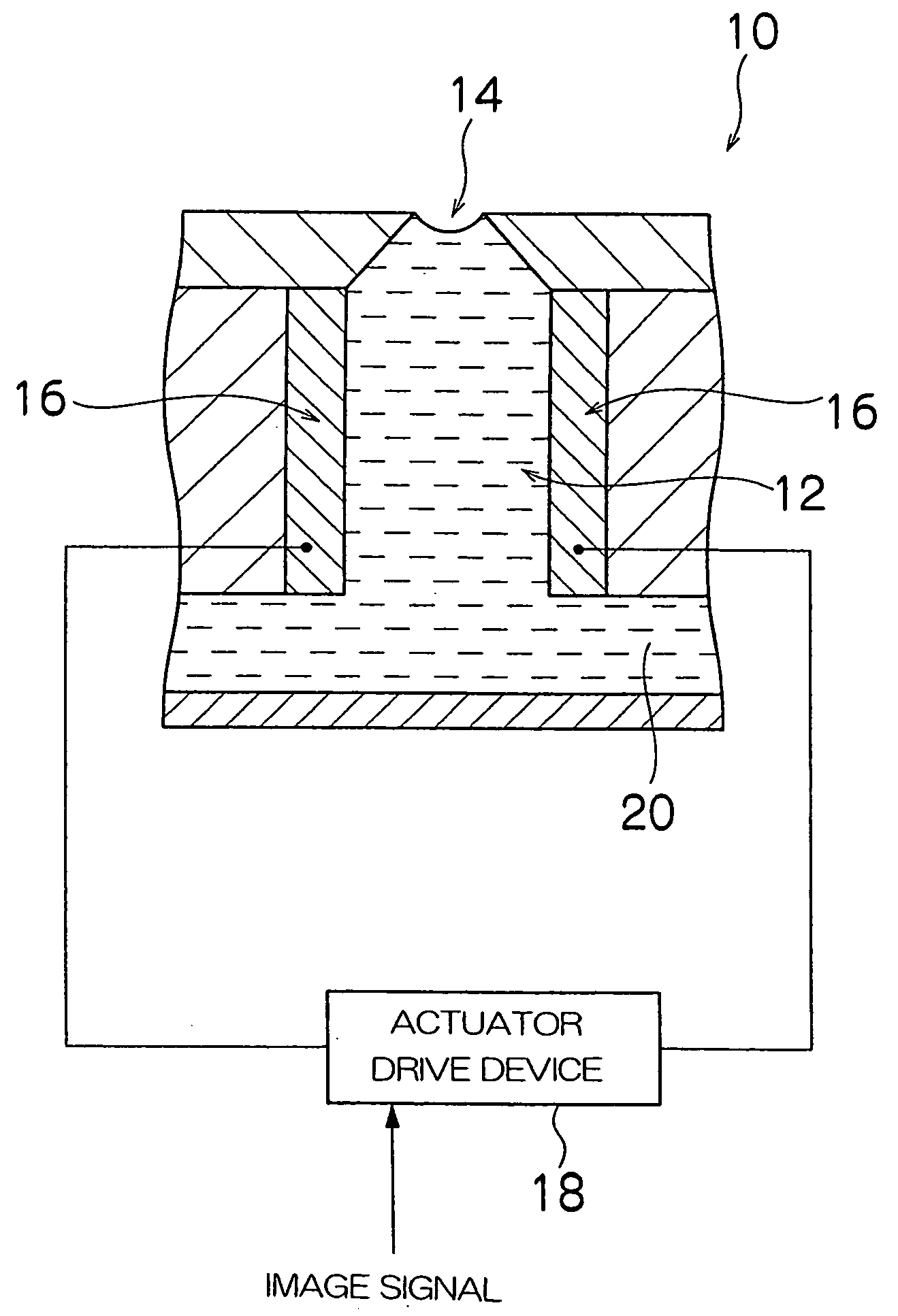
[0033]FIG. 1 is a principal cross-sectional diagram showing an approximate view of one embodiment of a droplet discharging apparatus relating to the present invention. As shown in FIG. 1, the droplet discharging apparatus 10 according to the present embodiment comprises: a pressure chamber 12 for accommodating a liquid to be discharged; a nozzle 14 for discharging a liquid provided in one end of the pressure chamber 12, as a droplet; an actuator 16 for changing the volume of the pressure chamber 12 provided in the wall of the pressure chamber 12; an actuator drive device 18 for applying a drive waveform to an actuator 16 in accordance with an image signal; and a liquid supply passage 20, or the like, connected to a liquid tank (not illustrated), for supplying the liquid to the pressure chamber 12 from the liquid tank; or th...


PUM


Abstract

A droplet discharging method for discharging a liquid inside a pressure chamber as a droplet from a nozzle, by applying a drive waveform to an actuator for causing change in volume of the pressure chamber filled with the liquid, is characterized by that: by taking volume of the pressure chamber as V, taking cross-sectional surface area of the nozzle as A, taking a length of the nozzle as l0, taking a density of the liquid to be discharged as ρ, taking viscosity coefficient of the liquid to be discharged as μ, and taking rate of transmission of a pressure wave transmitted through the liquid inside the pressure chamber as c, these respective factors are established in such a manner that a condition expressed by the following inequality expression is satisfied: c2V<16π2·µ2·l0A3·ρ2.

Description

BACKGROUND OF THE INVENTION [0001] 1. Field of the Invention [0002] The present invention relates to a droplet discharging method and apparatus, and more particularly, to a droplet discharging method and apparatus whereby a liquid, such as ink with high viscosity, or the like, can be discharged at a sufficient speed in the form of a minute droplet, by means of an inkjet method. [0003] 2. Description of the Related Art [0004] A droplet discharging apparatus according to an inkjet method records images, or the like, by discharging a liquid, such as ink, or the like, towards a recording medium, as droplets, from nozzles formed on the recording head. There are various ink discharging methods for an ink droplet discharging apparatus based on an inkjet method, and a method is known, for example, whereby the volume of a pressure chamber is caused to change by means of deformation of a piezoelectric ceramic, ink is provided into the pressure chamber from an ink supply passage when the volum...

Claims


Application Information

Patent Timeline
IPC IPC(8): B41J2/045B41J2/14
CPCB41J2/04571B41J2/04581B41J2202/11B41J2/14209B41J2/04588
Inventor MATAKI, HIROSHI
Owner FUJIFILM CORP
Why Eureka
Try Eureka