Component having a micromechanical microphone structure, and method for its production

Inactive Publication Date: 2012-04-19
ROBERT BOSCH GMBH
View PDF11 Cites 15 Cited by
  • Summary
  • Abstract
  • Description
  • Claims
  • Application Information

AI Technical Summary

Benefits of technology

[0019]The use of a SiGe sacrificial layer using ClF3 as etching gas is especially advantageous due to the high selectivity of the etching process with regard to numerous materials used in micro-system technology, and with regard to silicon, in particular. This etching process is characterized by its high etching speed and the large under-etching widths obtainable in this manner. In addition, SiGe sacrificial layers are especially low in stresses, so that the use of this material also allows relatively thick sacrificial layers and thus large electrode clearances to be realized, without introducing additional stresses in the component configuration. This increases the design freedom in the configuration of the microphone component.
[0020]As mentioned already, the microphone structures according to the present invention are exposed in the wafer composite and separated only thereafter. One especially advantageous variant of the method according to the present invention utilizes the configuration of the microphone component according to the present invention, i.e., the fact that the layer in which the counter elements are realized is situated on the top surface of the lay

Problems solved by technology

The highly fragile structure of the conventional microphone component, which is sensitive to water, poses a problem in this context.
The cost-efficient sawing with the aid of a water-cooled circular saw, which is very common in micro technology, cannot be used for these components without additional protective measures.
It must be assumed that the sensitive microphone structures are unable to withstand the impinging water jet.
In addition, water that

Method used


Image

  • Component having a micromechanical microphone structure, and method for its production
  • Component having a micromechanical microphone structure, and method for its production
  • Component having a micromechanical microphone structure, and method for its production

Examples


Embodiment Construction

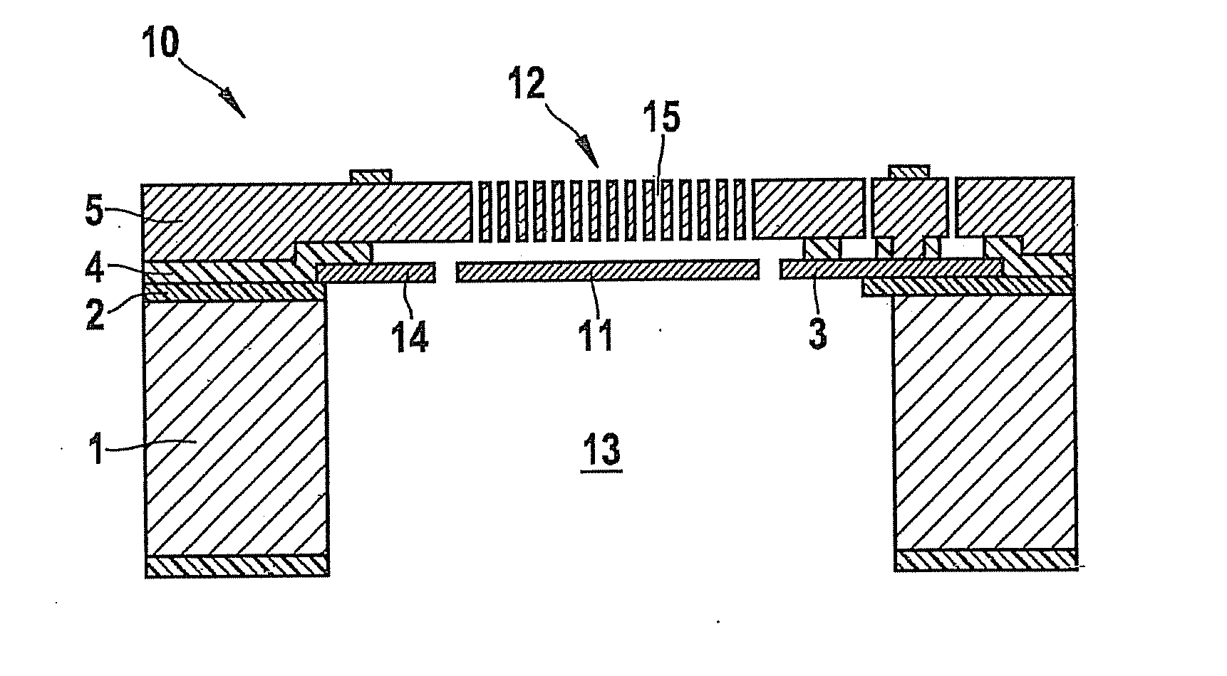
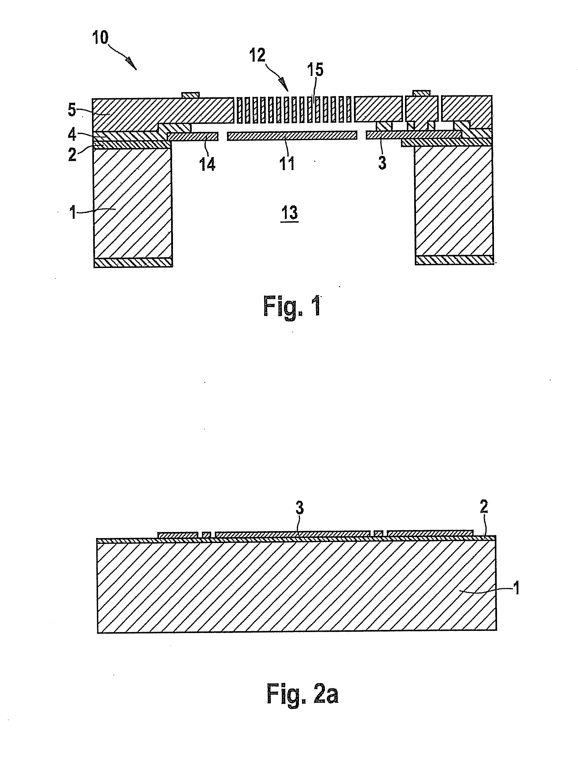
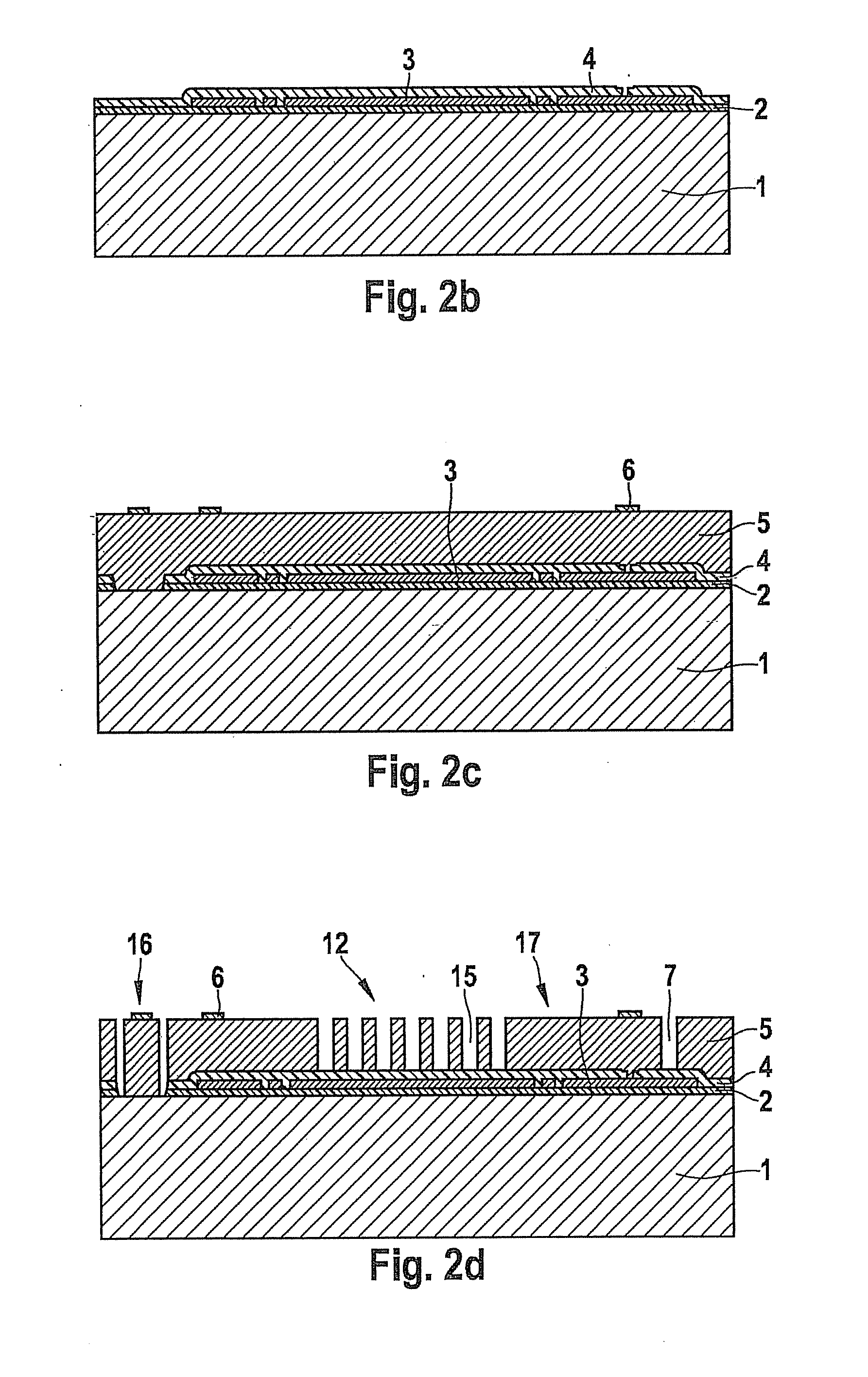
[0027]Component 10 shown in FIG. 1 includes a micromechanical microphone structure having a deflectable, acoustically active diaphragm 11, and a stationary, acoustically permeable counter element 12, which is also referred to as back plate. Here, diaphragm 11 and counter element 12 are realized in a layer configuration on a semiconductor substrate 1. A sound opening 13, which extends across the entire thickness of semiconductor substrate 1 and which is spanned by diaphragm 11 disposed on the top side of semiconductor substrate 1, is developed on the rear side of semiconductor substrate 1. Diaphragm 11 is realized in a thin polysilicon layer 3 and electrically insulated from semiconductor substrate 1 by a first insulation layer 2. The deflectability of thin diaphragm 11 is enhanced by its spring suspension 14 formed in polysilicon layer 3. In contrast, counter element 12 is developed in a relatively thick epi-polysilicon layer 5 above diaphragm 11 and fixedly connected to the layer c...


PUM


Abstract

A component having a robust, but acoustically sensitive microphone structure is provided and a simple and cost-effective method for its production. This microphone structure includes an acoustically active diaphragm, which functions as deflectable electrode of a microphone capacitor, a stationary, acoustically permeable counter element, which functions as counter electrode of the microphone capacitor, and an arrangement for detecting and analyzing the capacitance changes of the microphone capacitor. The diaphragm is realized in a diaphragm layer above the semiconductor substrate of the component and covers a sound opening in the substrate rear. The counter element is developed in a further layer above the diaphragm. This further layer generally extends across the entire component surface and compensates level differences, so that the entire component surface is largely planar according to this additional layer. This allows a foil to be applied on the layer configuration of the microphone structures exposed in the wafer composite, which makes it possible to dice up the components in a standard sawing process.

Description

BACKGROUND INFORMATION[0001]The present invention relates to a component having a micromechanical microphone structure. The microphone structure includes an acoustically active diaphragm, which functions as deflectable electrode of a microphone capacitor, a stationary, acoustically permeable counter element, which functions as counter electrode of the microphone capacitor, and means for detecting and analyzing the capacitance changes of the microphone capacitor. The diaphragm is realized in a diaphragm layer above the semiconductor substrate of the component and spans a sound opening in the substrate rear. The counter element is developed in an additional layer above the diaphragm.[0002]Furthermore, the present invention relates to a method for producing such components in the wafer composite and subsequent dice-up operation.[0003]U.S. Patent Application Publication No. 2002 / 0067663 A1 describes a microphone component whose micromechanical microphone structure is realized in a layer...

Claims


Application Information

Patent Timeline
IPC IPC(8): H01L29/84H01L21/02
CPCH04R19/005Y10T428/31663
Inventor REICHENBACH, FRANKBUCK, THOMASZOELLIN, JOCHENLAERMER, FRANZSCHOLZ, ULRIKETEEFFELEN, KATHRIN VANLEINENBACH, CHRISTINA
Owner ROBERT BOSCH GMBH
Why Eureka
Try Eureka