
Image pickup apparatus and range determination system

Active Publication Date: 2011-09-08
RICOH KK
View PDF5 Cites 13 Cited by
  • Summary
  • Abstract
  • Description
  • Claims
  • Application Information

AI Technical Summary

Benefits of technology

[0013]The present invention was conceived in view of the above-described technical problems in the prior art, and it is an objective to provide an image pickup apparatus with improved accuracy in range determination. This objective can be achieved by dividing a multifaceted compound-eye image taken by image pickup elements into monocular images, detecting a subject with a known positional relationship relative to the image pickup apparatus from each of the monocular images, determining a distortion parameter based upon a position of the detected subject, and correcting the distortion of each of the monocular images using the distortion parameter.
[0023]By recognizing the image pickup position of a reference subject externally existing, range determination errors due to a temperature change can be reduced. By using a marker as the reference subject, the positional displacement of the reference subject can be detected precisely. When providing a marker in the system, it is unnecessary to prepare an external reference subject outside the image pickup apparatus, and a possible problem that may arise when using an external marker can be prevented. An example of such a problem is that the external reference subject may not be detected if another object exists between the external reference subject and the image pickup apparatus. By structuring a system using a combination of an image pickup apparatus and a marker, freedom of design will increase, and distortion or positional displacement of the reference markers (subject) can be determined more precisely.

Problems solved by technology

However, it is generally known that variations in the environmental temperatures cause the lens shape of an image pickup apparatus to change, and that the optical conditions inevitably change.
Especially when using a range determination device with a short baseline length, such as a system disclosed in the above-described Patent Document 2 employing a combination of an image pickup sensor and a lens array to carry out range measurement, the ratio of change in the baseline length due to a temperature change is great, and therefore the range determination result is significantly affected.
However, this method requires a temperature to be sensed although not explicitly described.
In addition, influence of the device variability cannot be completely removed.

Method used


Image

  • Image pickup apparatus and range determination system
  • Image pickup apparatus and range determination system
  • Image pickup apparatus and range determination system

Examples


Embodiment Construction

[0035]The preferred embodiments of the present invention will now be described below in conjunction with the attached drawings. It should be noted that the invention is not limited to the structural components, forms, combinations, shapes, relative layout, or the like described below, and that these structures are exhibited for the exemplifying purpose only.

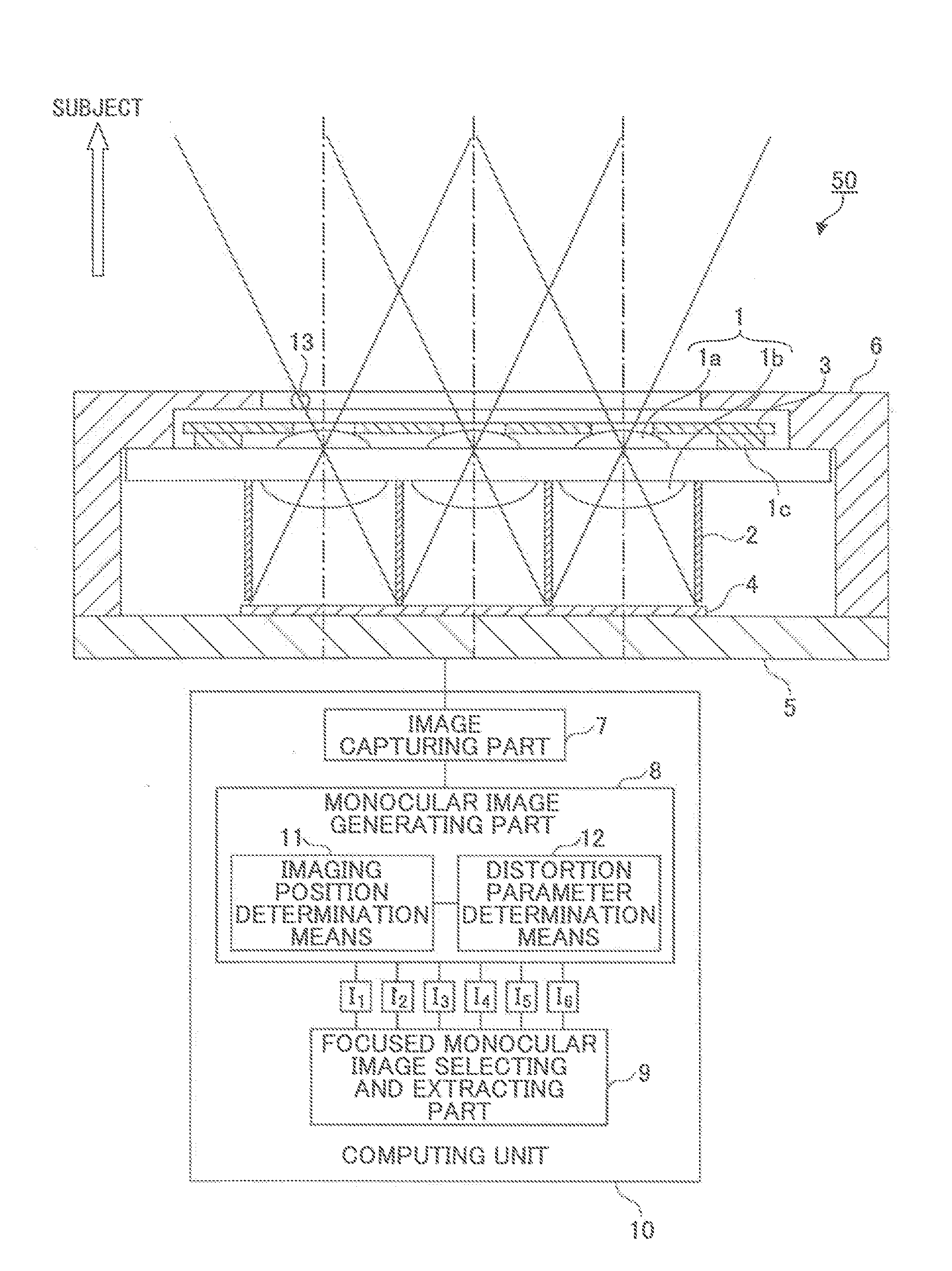
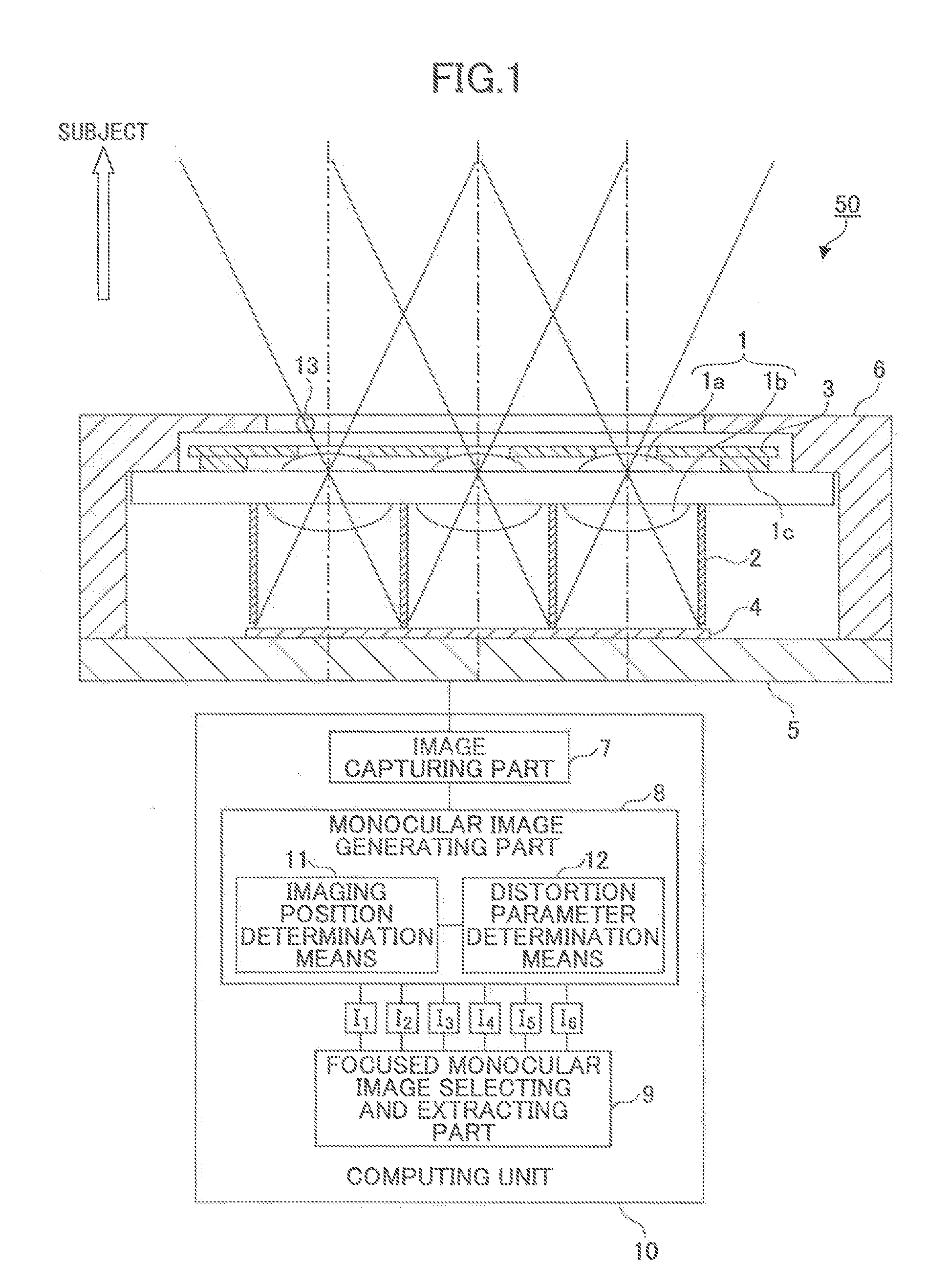
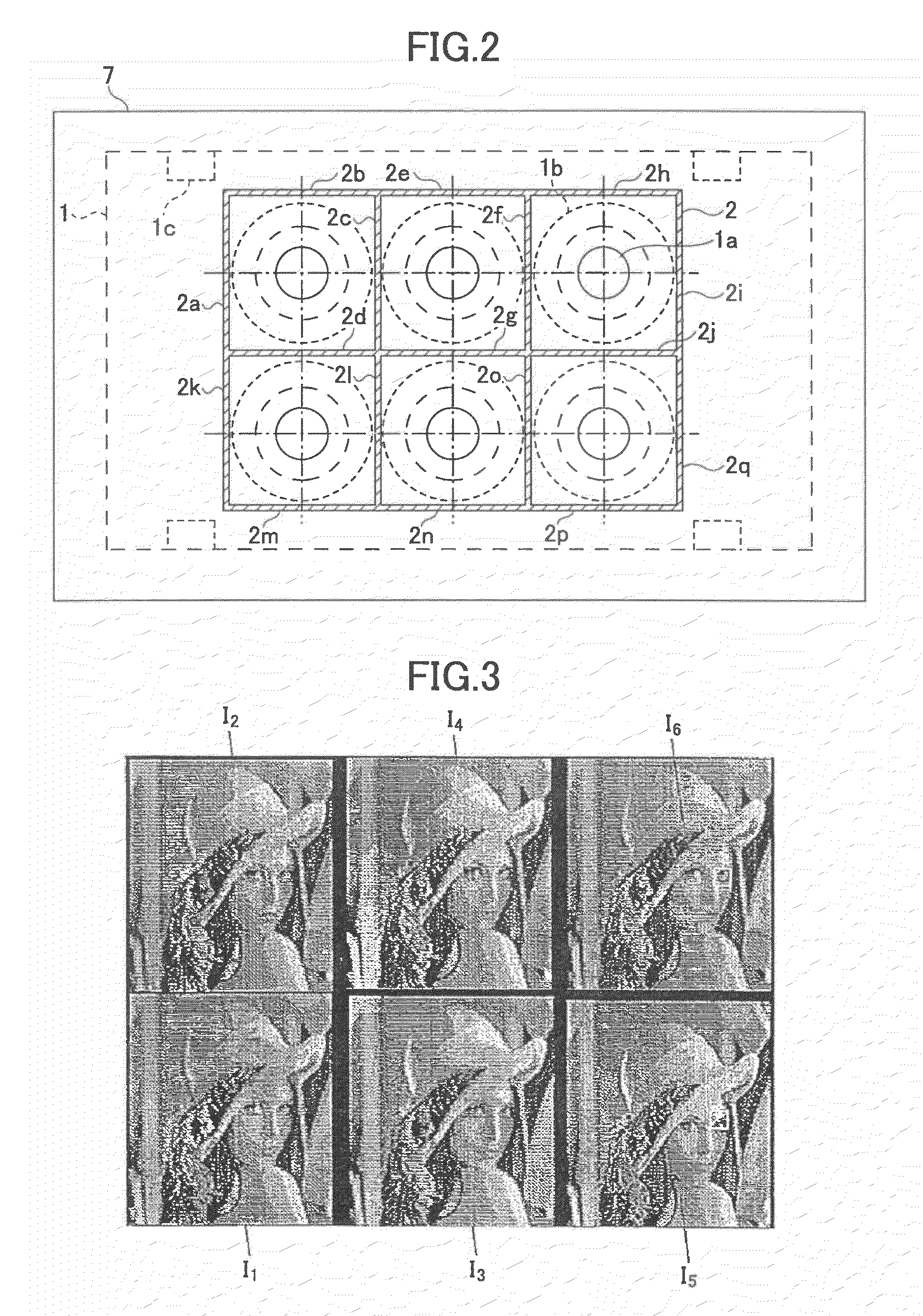
[0036]FIG. 1 is a schematic diagram showing an example of the image pickup apparatus according to an embodiment of the invention. The image pickup apparatus 50 is placed so as to face a subject (not shown) to be taken, and includes a lens array 1 and a CMOS sensor (i.e., an image pickup device) 4 positioned on the image-plane side of the lens array 1. The lens array 1 has multiple lenses 1a and multiple lenses 1b arranged in an array. The CMOS sensor 4 takes a multifaceted compound-eye image consisting of a set of demagnified images (which images are referred to as “monocular images”) formed by the multiple lenses 1a and 1b. The ...


PUM


Abstract

An image pickup apparatus comprises a lens array with a plurality of lenses, a part of which lenses makes one or more stereo lens pairs; an image pickup device for taking a multifaceted compound-eye image consisting of a set of monocular images formed by the plural lenses; and a computing unit for computing range imagery from one or more pairs of the monocular images formed by said one or more stereo lens pairs. The computing unit includes imaging position determination means for determining from the monocular images an image pickup position of each of one or more subjects whose relative positional relationships with respect to the image pickup apparatus are known by dividing the multifaceted compound-eye image into the monocular images, and image distortion parameter determination means for determining an image distortion parameter based upon a determination result of the imaging position determination means.

Description

TECHNICAL FIELD[0001]The present invention generally relates to an image pickup apparatus, and more particularly, to a technique for correcting optical conditions that vary according to an environmental temperature change to improve accuracy of range determination.BACKGROUND ART[0002]Image pickup apparatuses are useful instruments for acquiring image information and applied to various fields such as portable appliances, in-vehicle equipment, medical instruments and equipment, and industrial instruments and equipment. A demand for more intelligent range imagery input apparatuses capable of acquiring not only two-dimensional image data, but also range information including a distance from a subject and a three-dimensional shape of the subject is also increasing. Such range imagery input apparatuses are actually used in various places. However, it is known that the lens shape of an image pickup apparatus varies and accordingly, the optical conditions of the apparatus change due to chan...

Claims


Application Information

Patent Timeline
IPC IPC(8): H04N5/228
CPCG06T7/0018G06T2207/10012G06T2207/30204H04N17/002H04N5/2258H04N5/3572G06T2207/30268G06T7/80H04N23/45H04N25/61
Inventor MARUYAMA, GOTAKAHASHI, SADAOHAGIYA, TOSHIMICHIWATANABE, JUNAOKI, SHIN
Owner RICOH KK
Learn More