Imaging apparatus
a technology of imaging apparatus and spherical tube, which is applied in the field of imaging apparatus, can solve problems such as and achieve the effect of facilitating reducing the size of imaging apparatus
- Summary
- Abstract
- Description
- Claims
- Application Information
AI Technical Summary
Benefits of technology
Problems solved by technology
Method used
Image
Examples
first embodiment
[0015] There will be described a first embodiment of the invention, by reference to FIGS. 1 and 2.
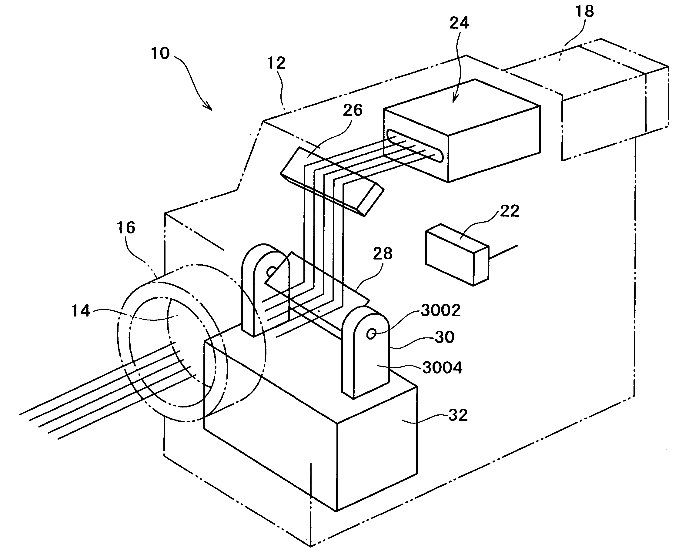
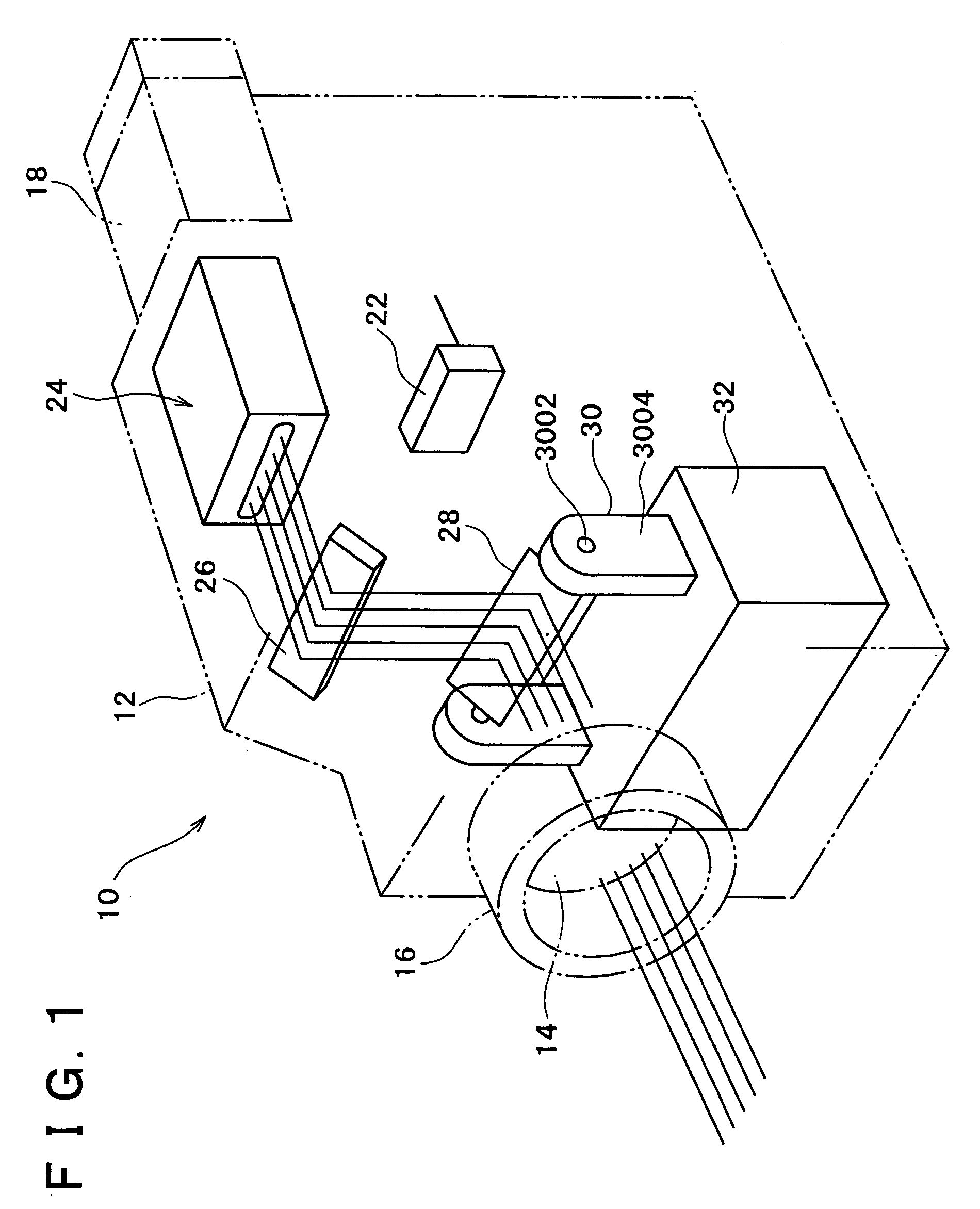
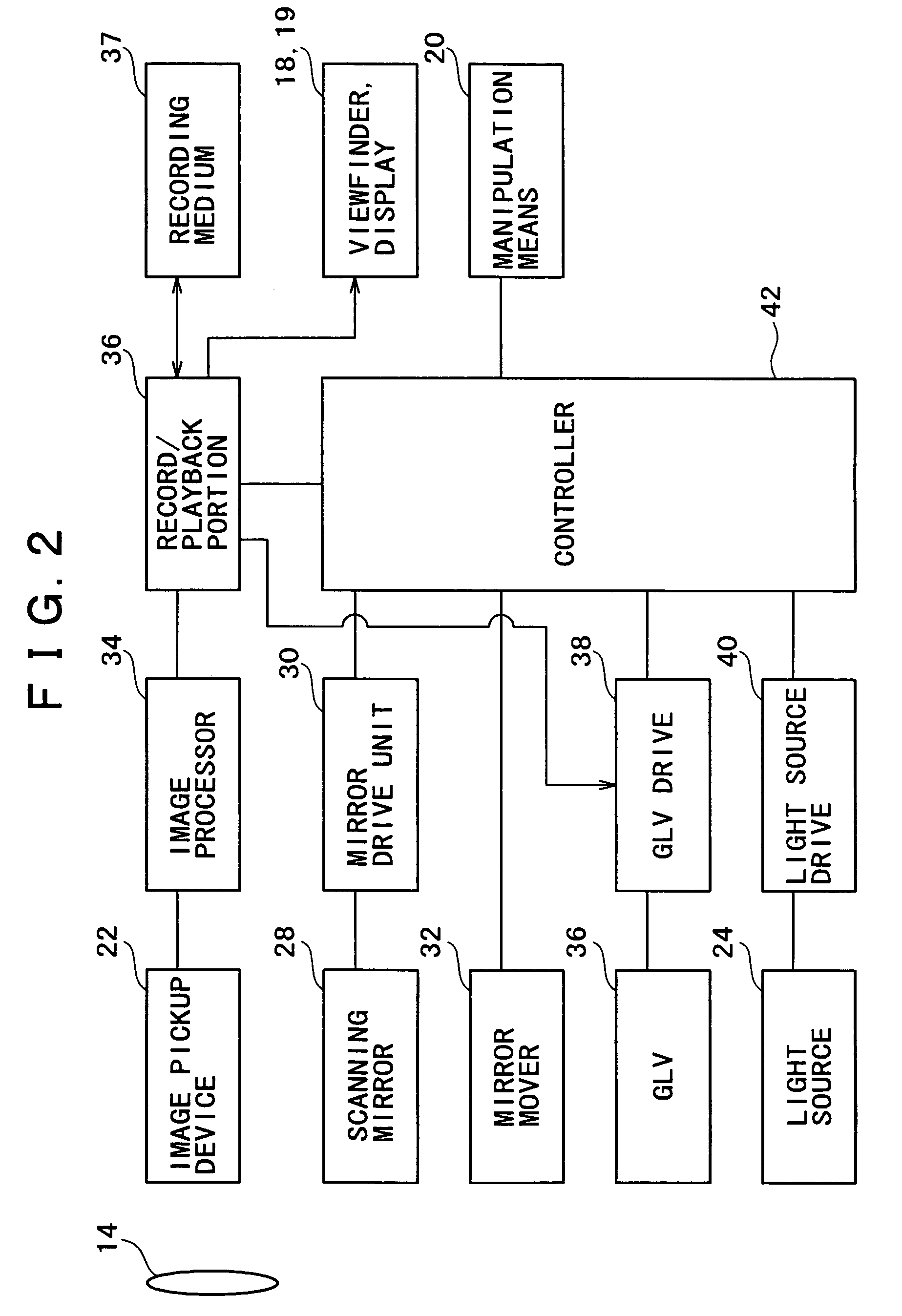
[0016]FIG. 1 is a perspective view showing a structure of an imaging apparatus 10 according to the first embodiment, while FIG. 2 is a block diagram showing the structure of the imaging apparatus 10.
[0017] As shown in FIG. 1, the imaging apparatus 10 is a video camera having a housing 12.
[0018] In the upper part of the front face of the housing 12, there is disposed a lens barrel 16 holding a taking lens 14, while in the upper part of the rear side of the housing 12 is disposed a viewfinder 18 having a liquid crystal display or the like.
[0019] On the lateral faces of the housing 12, there is disposed manipulation means 20 (indicated in FIG. 2) including an ON / OFF button, a shutter / video button, a play button and a mode button. The mode button is manipulated or switched for selecting whether the video camera 10 is to be operated as a usual video camera or as a projector.
[0020] A dis...
second embodiment
[0058] There will be now described a second embodiment of the invention, by reference to FIG. 3.
[0059]FIG. 3 is a perspective view showing a structure of an imaging apparatus 10 according to the second embodiment. The same or similar elements as the corresponding elements in the first embodiment are denoted by the same reference numerals and detailed description thereof is omitted.
[0060] The difference between the first and second embodiments is that the light source of the second embodiment is disposed outside the housing of the apparatus.
[0061] As shown in FIG. 3, inside a housing 12 of the imaging apparatus 10 are disposed an image pickup device 22, a GLV 26, a scanning mirror 28, a mirror drive unit 30, a mirror mover 32, etc, similarly to the first embodiment.
[0062] Outside the housing 12 is provided a light source 24 such that one of opposite ends of an optical fiber 25 is attached to the light source 24 to introduce, to the inside of the housing 12, lights emitted from re...
PUM
 Abstract
Description
Claims
Application Information
 - R&D
- Intellectual Property
- Life Sciences
- Materials
- Tech Scout
- Unparalleled Data Quality
- Higher Quality Content
- 60% Fewer Hallucinations
Browse by: Latest US Patents, China's latest patents, Technical Efficacy Thesaurus, Application Domain, Technology Topic, Popular Technical Reports.
© 2025 PatSnap. All rights reserved.Legal|Privacy policy|Modern Slavery Act Transparency Statement|Sitemap|About US| Contact US: help@patsnap.com


