Optical pick-up device with respective flush screws eccentrically positioned between an actuator base and a magnetic holder, together between a printed-circuit board and a support member

a technology of optical pick-up device and flush screw, which is applied in the direction of disposition/mounting of heads, instruments, data recording, etc., can solve the problem of difficult to precisely position not only magnet holders, and achieve the effect of simple structure and low cos

Inactive Publication Date: 2005-05-12
FUNAI ELECTRIC CO LTD
View PDF5 Cites 2 Cited by
  • Summary
  • Abstract
  • Description
  • Claims
  • Application Information

AI Technical Summary

Benefits of technology

[0007] It is consequently an object of the present invention to provide an optical pick-up device having a cheap and simple structure capable of precisely positioning members assembled upon an actuator base.

Problems solved by technology

It is, however, disadvantageous in that it is difficult to precisely position not only a magnet holder 11 for holding a holder magnet 10 on an actuator base 1, but also a printed circuit board 15 on a support member 2 arranged on the actuator base 1.

Method used


Image

  • Optical pick-up device with respective flush screws eccentrically positioned between an actuator base and a magnetic holder, together between a printed-circuit board and a support member
  • Optical pick-up device with respective flush screws eccentrically positioned between an actuator base and a magnetic holder, together between a printed-circuit board and a support member
  • Optical pick-up device with respective flush screws eccentrically positioned between an actuator base and a magnetic holder, together between a printed-circuit board and a support member

Examples


Embodiment Construction

Description of the Related Art

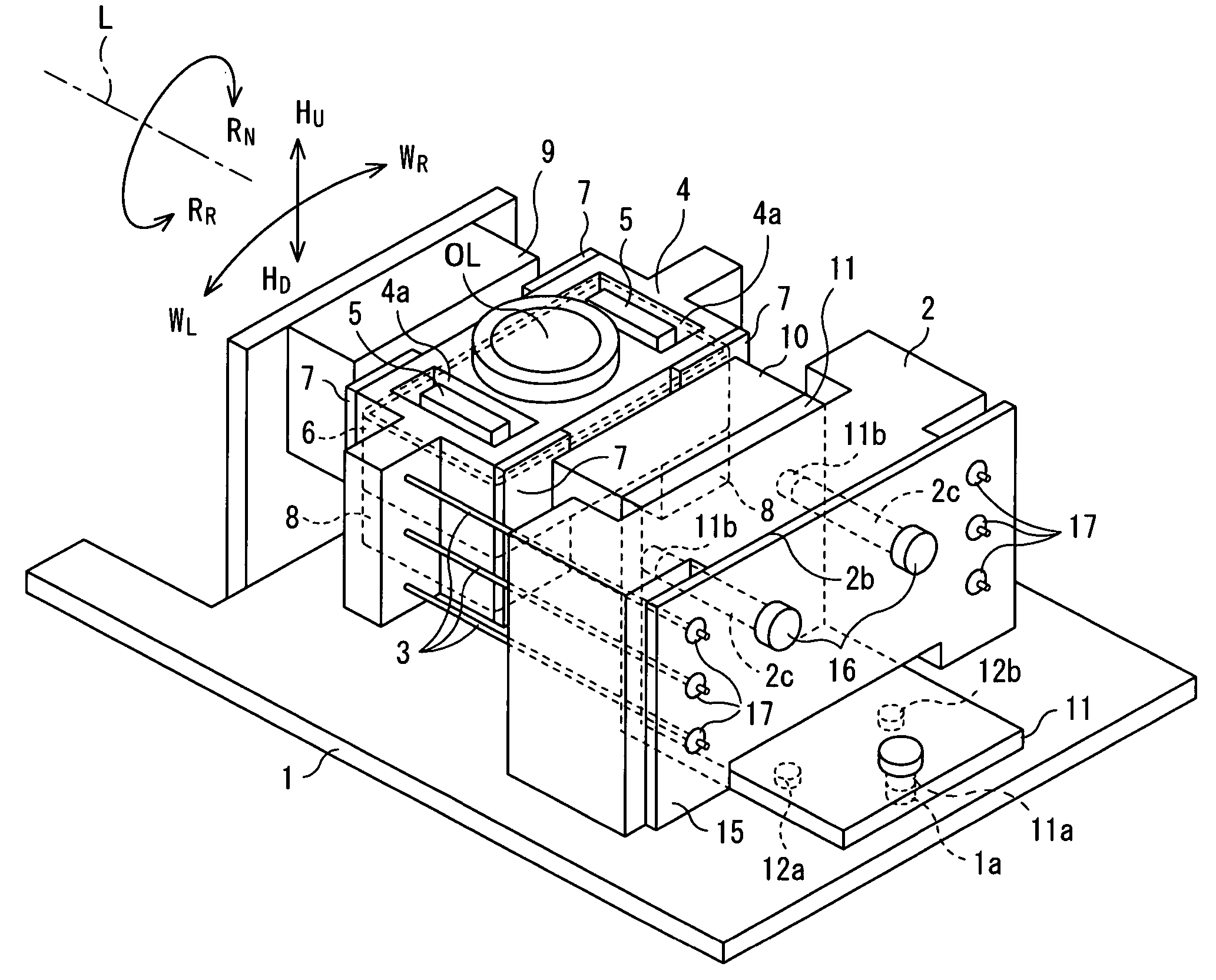
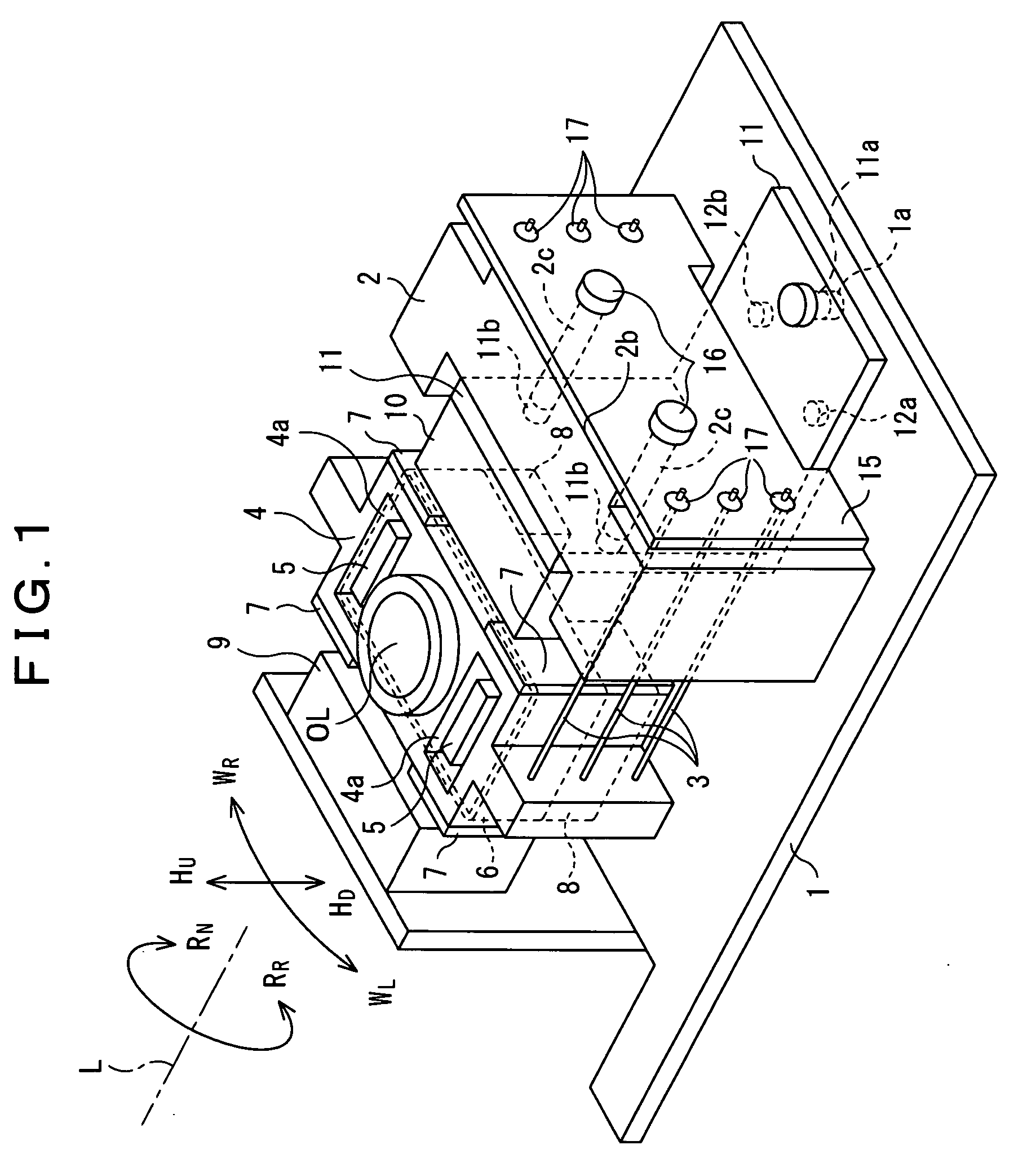
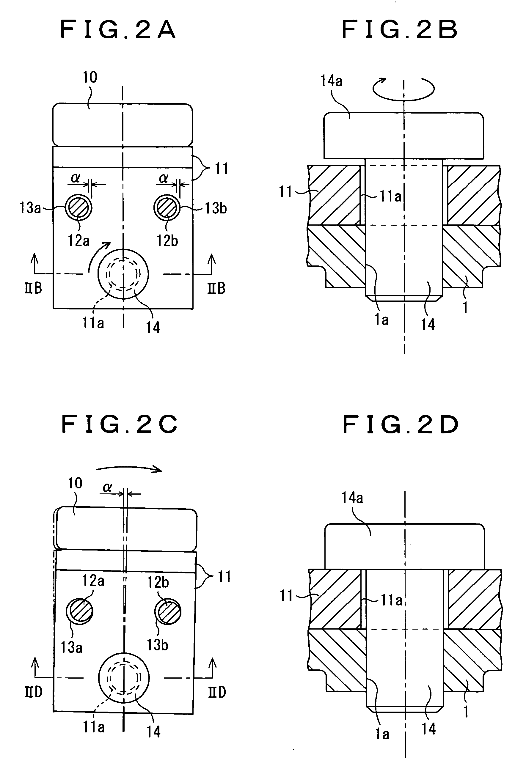
[0060] Referring now to FIGS. 1 through 3D, the related art optical pick-up device will be described in order to facilitate an understanding of the present invention.

[0061] The related art optical pick-up device comprises an actuator base 1, a support member 2 disposed upon one end of the actuator base 1, and a lens holder 4 with an objective lens OL facing the supporting member 2 upon the actuator base 1. The lens holder 4 has a pair of ends with a pair of yoke holes, a yoke 5 being inserted into each yoke hole. The lens holder 4 includes coil means of a focusing coil 6, a tracking coil 7, and a tilt coil 8.

[0062] The related art optical pick-up device further comprises a fixed magnet 9 adjacent to the lens holder 4 and fixed upon the other end of the actuator base 1, a holder magnet 10 facing the fixed magnet so as to interpose the lens holder 4, a magnet holder 11 having a holding portion with a holder hole 11a for holding the holder magnet 10 and...


PUM

PropertyMeasurementUnit
angleaaaaaaaaaa
angleaaaaaaaaaa
lengthaaaaaaaaaa

Abstract

In order to achieve an object of making an optical pick-up have a cheap and simple structure capable of precisely positioning members assembled upon an actuator base 1, the optical pick-up device make a use of respective flush screw members 19, 20 for a magnet holder 11 and for a printed-circuit board 15 eccentrically positioned between an actuator base 1 and a magnet holder 11, together with between the printed-circuit board 15 and the support member 2. The flush screw member 19 serves to be inserted through the holder hole 11a, to be firmly secured into the screw hole 1a, and to thereby prevent the pick-up device from being loosened, because of being provided with a predetermined eccentric distance t1 between a center of axle O1 of the screw hole 1a and a center of axle O2 of the holder hole 11a. Likewise, a triangle-shape opening 15b′-1 of the printed-circuit board 15 is adapted to receive the board flush screw 20, so that a slant tapered surface 20a of a board flush head 20-1 of the board flush screw 20 acts as an eccentrically fastener for fixture and positioning of the support member 2 and the printed-circuit board 15.

Description

BACKGROUND OF THE INVENTION [0001] 1. Field of the Invention [0002] The present invention relates to an optical pick-up device, in particular, an optical pick-up device used to a disk player for a DVD and / or a CD. The optical pick-up device used to the disk player is for reading information from the DVD and / or the CD. [0003] 2. Prior Art [0004] In the matter which will later be described more in detail, such optical pick-up devices are already known upon laying open of the following patent documents. As a first prior art example of the optical pick-up device, there is a patent document No.1 ((Japanese Patent Application, Unexamined Prepublication (A) Kokai No.222751 of 2000 (JP2000-222751A)) entitled “Biaxial Actuator for Optical Pick-up Device”. The first prior art device is provided with a damper box and a lens holder disposed upon an actuator base. Bridged with the lens holder, a plurality of resilient-conductive links are arranged with a first transit substrate (printed circuit ...

Claims


Application Information

Patent Timeline
Patent Type & Authority Applications(United States)
IPC IPC(8): G11B7/00G11B7/08
CPCG11B7/082
Inventor NOGAMI, TOYOSIMATSUMOTO, YOSHIMASA
Owner FUNAI ELECTRIC CO LTD
Why Eureka
Try Eureka