Front window shield for vehicle

A vehicle and front window technology is applied in the field of vehicle front windows, which can solve the problems of inability to reduce the burden of assembling operators, large number of parts, high cost, etc., and achieve the effect of simple and inexpensive structure

Active Publication Date: 2011-02-16
HONDA MOTOR CO LTD
View PDF6 Cites 0 Cited by
  • Summary
  • Abstract
  • Description
  • Claims
  • Application Information

AI Technical Summary

Problems solved by technology

Moreover, since a controller for controlling the liquid crystal panel is required, it is expensive
[0009] In the technologies described in the above-mentioned patent documents 3 and 4, since the center pillar or the camera is installed on the front side of the vehicle, the number of parts is large and the structure is complicated, and the burden on the assembly operator cannot be reduced.
Moreover, in the technology described in the above-mentioned Patent Document 3, when the corner bar is not used, it is controlled so that it is stored in the vehicle by electric power, so wiring and a controller need to be laid, and the cost is expensive.
In the technology described in the above-mentioned patent document 4, the image captured by the camera is displayed on the display in the car, so it is necessary to lay wiring and the display, which makes the cost expensive.

Method used


Image

  • Front window shield for vehicle
  • Front window shield for vehicle
  • Front window shield for vehicle

Examples


Embodiment approach 1

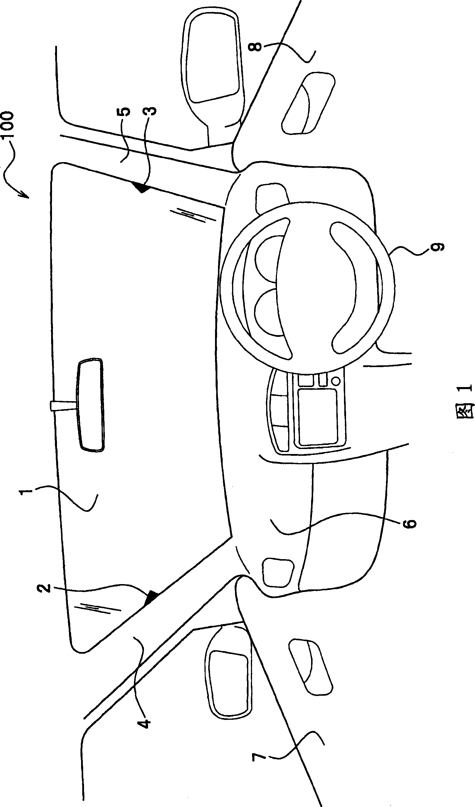
[0056] First, refer to figure 1 The schematic diagram shown is for explaining the vehicle windshield of the first embodiment. That is, the case where the vehicle comes into contact with a horizontal road surface will be described here.

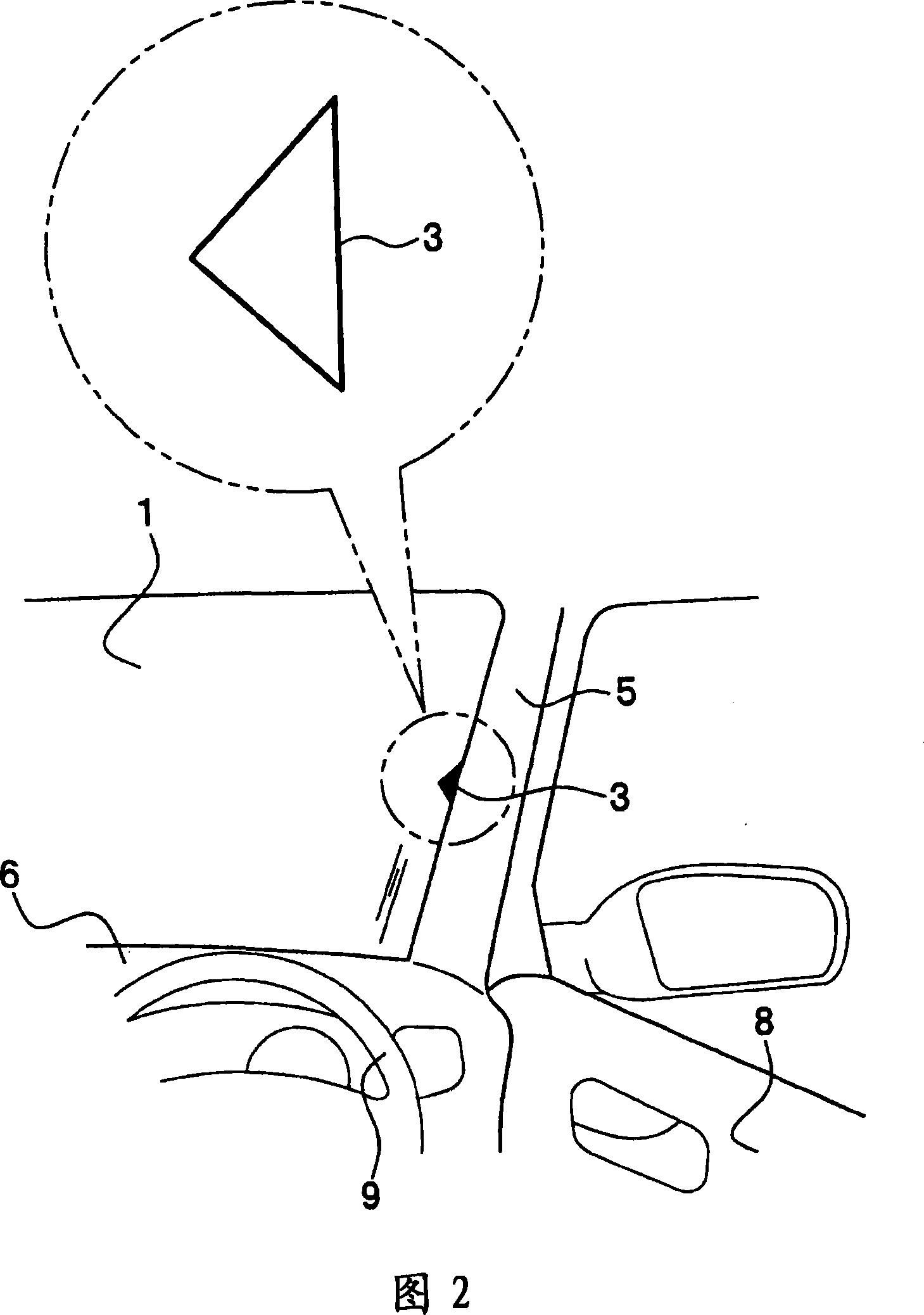
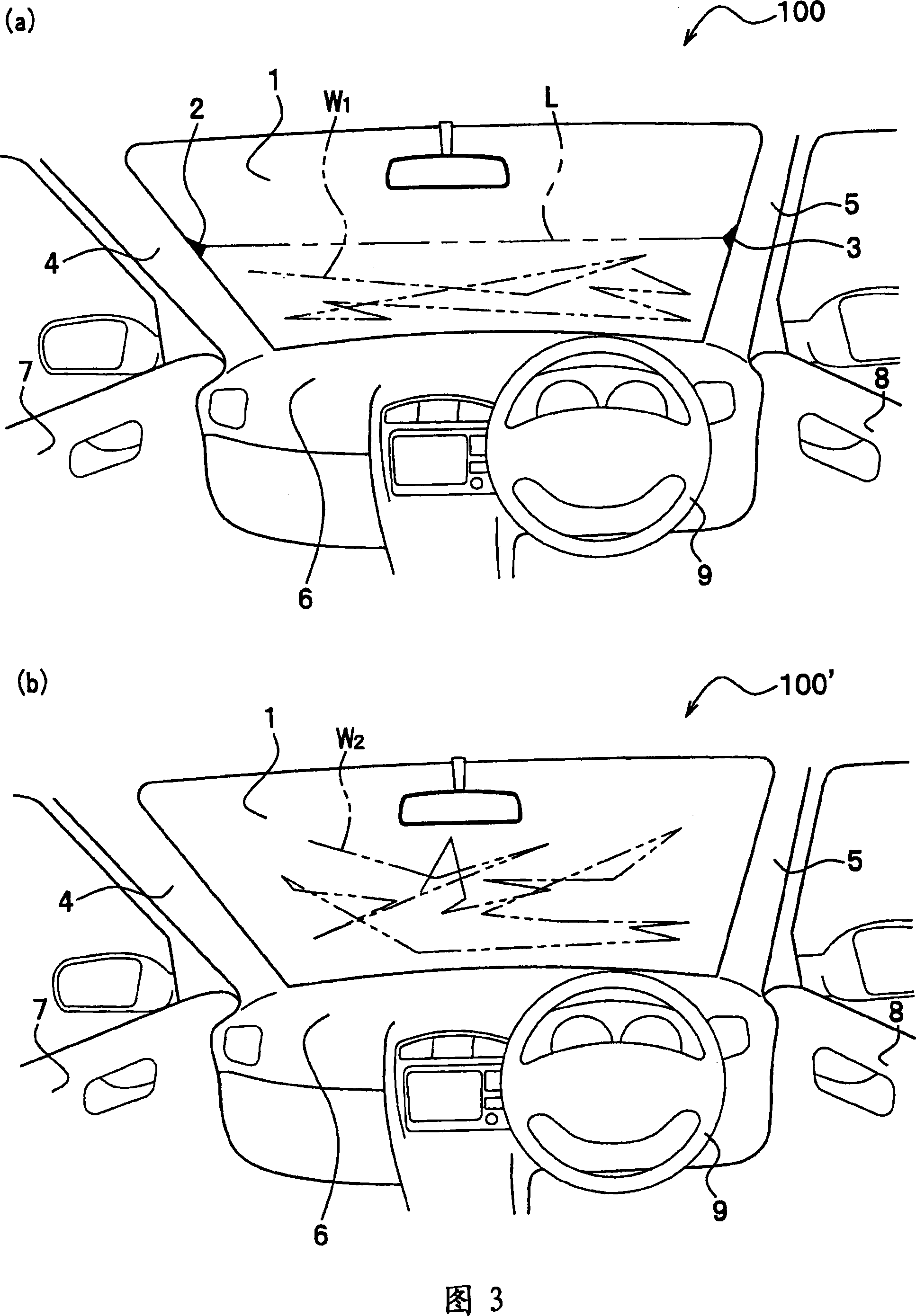
[0057] Such as figure 1 As shown, in this vehicle 100 , a pair of marks 2 and 3 showing a substantially horizontal direction are provided on a vehicle front window (hereinafter referred to as "front window") 1 . The marks 2 and 3 are formed at the same height positions on the left and right sides of the front window 1 . Accordingly, the driver can perceive an imaginary straight line connecting the pair of marks 2 and 3 .

[0058] The markings 2, 3 are formed of so-called black ceramic prints (hereinafter referred to as "black porcelain"). Therefore, when black porcelain is formed on the edge of the glass of the front window 1 etc., the marks 2 and 3 may be formed on the front window 1 by making a part of it into a pair of isosceles trian...

Embodiment approach 2

[0089] Next, refer to Figure 8 The schematic diagram shown is for explaining the front window of Embodiment 2. FIG. and, in Figure 8 In, symbols 1, 4, 5, 6, 7, 8, 9 and figure 1 All parts shown are the same. In this vehicle 300 , regions 1 a , 1 b having lower transmittance than the high transmittance region of the windshield 1 are formed at the center of the upper and lower portions of the windshield 1 . Therefore, the regions with high transmittance other than the regions 1a and 1b with low transmittance are formed in a substantially H-shape.

[0090] Furthermore, the difference in transmittance between the high region and the low region may be any different ratio as long as the two can be distinguished. Furthermore, the regions 1a and 1b may be formed so that the transmittance changes when viewed from the driver's seat side (here, the right side). The regions 1 a and 1 b are formed by sandblasting the front window 1 , but they are not limited to this as long as the ...

Embodiment approach 3

[0098] Next, refer to Figure 9 The schematic diagram shown is for explaining the vehicle windshield of Embodiment 3. FIG. and, in Figure 9 In, symbols 1, 4, 5, 6, 7, 8, 9 and figure 1All parts shown are the same. In this vehicle 400 , when viewed from the driver's seat, the lower edge portion B of the windshield 1 has a substantially horizontal straight line shape, and the left end of the lower edge portion B intersects the horizontal waistline A on the left front pillar 4 . , the right end of its lower edge portion B crosses with the horizontal waistline C on the right front post 5 . That is, the lower end edge B and the waistlines A and C are at the same height.

[0099] The lower end edge B is formed in a substantially horizontal curved shape, and is formed of black porcelain (edge ​​auxiliary body) 1c formed in a substantially horizontal linear shape visually viewed from the driver's seat. Since the front window 1 is formed in a curved shape protruding forward, the...


PUM


Abstract

The invention relates to a front window shield for vehicle, and a vehicle having a simple and inexpensive structure that assists the driving sense is also provided. A front windscreen (1) of a vehicle (100) is provided with a pair of marks (2 and 3) substantially horizontally aligned. The marks (2 and 3) are formed at the same height at the left and right sides of the front windscreen (1). A driver perceives a virtual line (L) by the marks (2 and 3) on the front windscreen (1), and trackings of the line of sight (W1) are induced to move such as to gather between the bottom end line, for example a line of an instrument panel (6) and a virtual line (L).

Description

technical field [0001] The present invention relates to a vehicle front window having a simple and inexpensive structure that assists driving feeling. Background technique [0002] Conventionally, there is known a technique of installing a liquid crystal panel on the lower surface of a windshield (windshield) for a vehicle, applying a voltage to the liquid crystal panel according to the driving state, reducing the transmittance of the liquid crystal panel, and forcing the driver's line of sight to be positioned closer than the liquid crystal panel. An upper region with high transmittance (for example, refer to Patent Documents 1 and 2). [0003] In addition, there is known a technique in which a corner bar is provided at a vehicle end such as the front end of the passenger seat, and by using the corner bar that can be seen through the front window, it is possible to predict a vehicle end that cannot be directly seen from the inside of the vehicle (such as , refer to Patent ...

Claims


Application Information

Patent Timeline
Patent Type & Authority Patents(China)
IPC IPC(8): B60K35/00B60R1/00
Inventor 藤本直登志由本诚二奥山晴子田口克昭
Owner HONDA MOTOR CO LTD
Why Eureka
Try Eureka