Fuel injection device for I.C. engine

A technology for a fuel injection device and an internal combustion engine, which is applied to a fuel injection device, a fuel injection device with an oil accumulator, a combustion engine, etc., can solve problems such as time-consuming, and achieve the effect of stabilizing the switching time.

Inactive Publication Date: 2003-05-07
ROBERT BOSCH GMBH
View PDF2 Cites 1 Cited by
  • Summary
  • Abstract
  • Description
  • Claims
  • Application Information

AI Technical Summary

Problems solved by technology

[0004] In principle, the known fuel injection devices require two precisely operating and therefore complex 3 / 2-control solenoid valves for each individual injector in order to be able to precisely meter the required fuel quantity and the required additional fluid quantity

Method used


Image

  • Fuel injection device for I.C. engine
  • Fuel injection device for I.C. engine
  • Fuel injection device for I.C. engine

Examples


Embodiment Construction

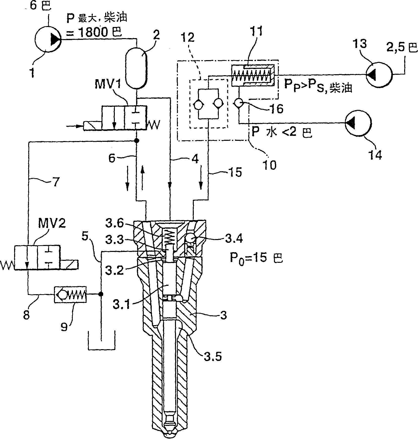
[0019] exist figure 1 In the shown first embodiment of the internal combustion engine fuel injection device for injecting fuel (usually diesel oil) and an additive liquid (usually water) two-fluid according to the present invention, a high-pressure pump 1 feeds the common rail-accumulator Unit 2 supplies fuel at a pressure level of approximately 1800 bar. Because the previously conventionally used fuel injection pump is replaced by a combination of the common rail-accumulator 2 and a simple high-pressure pump 1 and there is always a certain level of rail-pressure, now, in the common rail-accumulator 2 A dosing element must be installed between the pressure accumulator and the pressure chamber 3.5 surrounding the injection needle 3.1 of the double-material nozzle 3, which is supplied with fuel from the pressure accumulator via an injection line 6. In the configuration of the invention, a first 2 / 2-way valve MV1 takes over this task. The valve should be designed as a fast sole...


PUM


Abstract

A fuel injection system with a common rail pressure accumulator (2) filled with fuel under high pressure and a binary nozzle (3) for injecting two fluids, a fluid fuel and an additional liquid, into an internal combustion engine, comprises a first 2 / 2-port valve (MV1) arranged in the injection line (6) between the common rail pressure accumulator (2) and a pressure chamber (3.5) that surrounds the needle (3.1) of the binary nozzle (3), and also a second 2 / 2-port valve (MV2) whose inlet is connected through a supply line (7) to the injection line (6) at a point located between the first 2 / 2-port valve (MV1) and the pressure chamber (3.5), and whose outlet is connected through a discharge line (8) to the fuel low pressure side. This makes it possible to replace the otherwise common, considerably more complex 3 / 2-port magnetic control valves by more cost-effective 2 / 2-port valves. At the same time, this makes it possible to use a single metering valve which actuates a whole group of injectors for metering the additional liquid.

Description

technical field [0001] The invention relates to an oil injection device for an internal combustion engine. Background technique [0002] Such an oil injection device is known, for example, from DE 43 37 048 C2. In this fuel injection system, on the one hand, a dual-substance nozzle is provided for the layered injection of fuel and an additive liquid, such as diesel oil and water, in order to reduce the emission of harmful substances and possibly increase the efficiency of the internal combustion engine . On the other hand, the so-called Common-Rail technology is also implemented in known fuel injection devices, in which all fuel injectors operating the internal combustion engine are supplied with high pressure from the Common-Rail—the pressure accumulator Oil. [0003] The disadvantage of this known injection device is that each individual injector for metering the additive fluid requires a complex and relatively expensive 3 / 2-way valve and another 3 / 2 for controlling the...

Claims


Application Information

Patent Timeline
Patent Type & Authority Patents(China)
IPC IPC(8): F02M25/022F02B3/06F02M43/00F02M43/02F02M43/04F02M47/00F02M47/02F02M63/00
CPCF02B3/06F02M47/027F02M43/02F02M43/00F02M43/04F02M2200/40
Inventor 曼弗雷德·劳夫霍斯特·哈恩多夫
Owner ROBERT BOSCH GMBH
Why Eureka
Try Eureka