
System and method of dynamically optimizing a transmission mode of wirelessly transmitted information

a transmission mode and wireless transmission technology, applied in the field of wireless communication, can solve the problems of high bit-error rate, significantly lower parameter values, and excessive corruption

Inactive Publication Date: 2005-05-12
APPLE INC
View PDF15 Cites 98 Cited by
  • Summary
  • Abstract
  • Description
  • Claims
  • Application Information

AI Technical Summary

Benefits of technology

The invention is about an apparatus and method for optimizing the transmission mode of data transmitted to users in a wireless cellular system. The apparatus includes a look-up-table that selects the best transmission mode based on the characteristics of the channel. The method involves measuring the quality of the received data and adjusting the quality parameters in the look-up-table accordingly. The invention can be used in MIMO systems and can adapt to changes in the channel characteristics over time. The technical effects of the invention include improved data transmission reliability and efficiency.

Problems solved by technology

This goal is complicated because wireless communications channels between transmit and receive devices are inherently variable, so the characteristics of wireless channels, such as signal quality, generally vary in time, frequency and space.
However, under poor channel conditions, these parameters have significantly lower values.
For example, when the wireless channel is degraded the transmitted data may experience excessive corruption, manifesting as high bit-error rates or packet error rates.
In wireless systems (mobile and fixed), signal degradation and corruption is primarily due to interference from other cellular users within or near a given cell and multipath fading, in which the received amplitude and phase of a signal varies over time.
In both SISO and MIMO systems, however, the fundamental problem of efficient choice of the mode to be applied to the transmitted data remains.

Method used


Image

  • System and method of dynamically optimizing a transmission mode of wirelessly transmitted information
  • System and method of dynamically optimizing a transmission mode of wirelessly transmitted information
  • System and method of dynamically optimizing a transmission mode of wirelessly transmitted information

Examples


Embodiment Construction

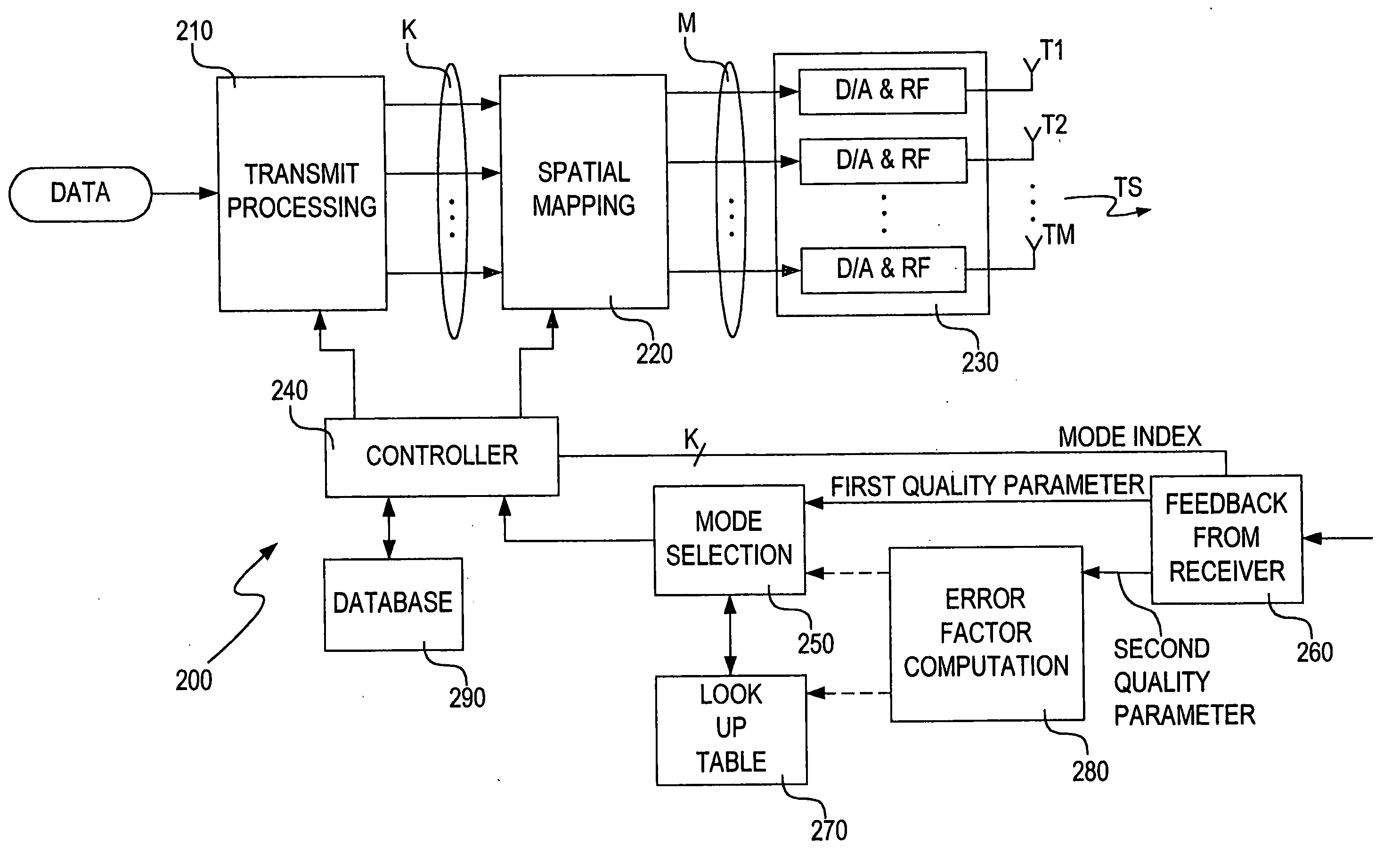
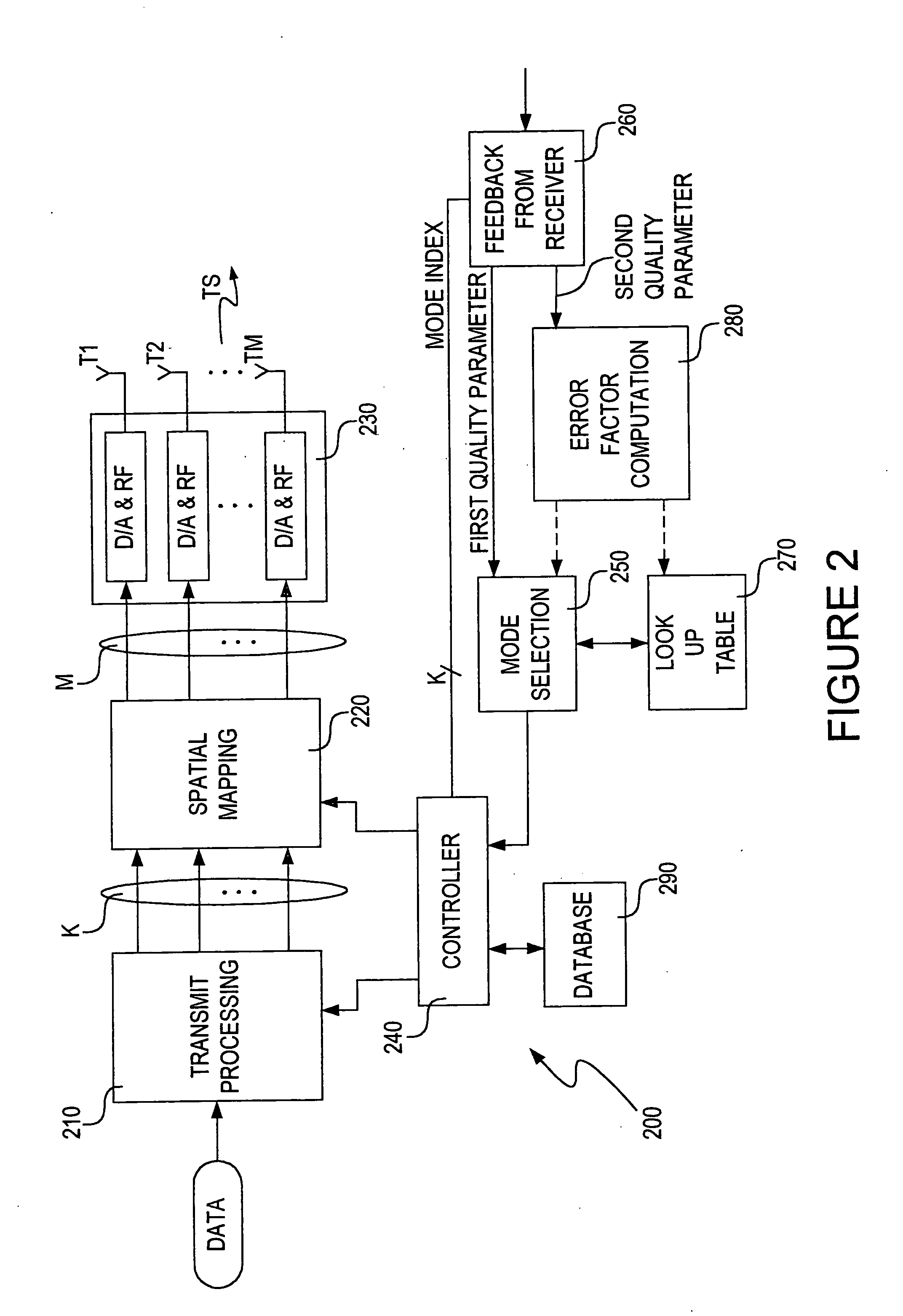
[0029] As shown in the drawings for purposes of illustration, the invention is embodied in an apparatus and a method for adaptively selecting a transmission mode for the transmission of data to users within a wireless cellular system. The invention can include multiple antennae systems.

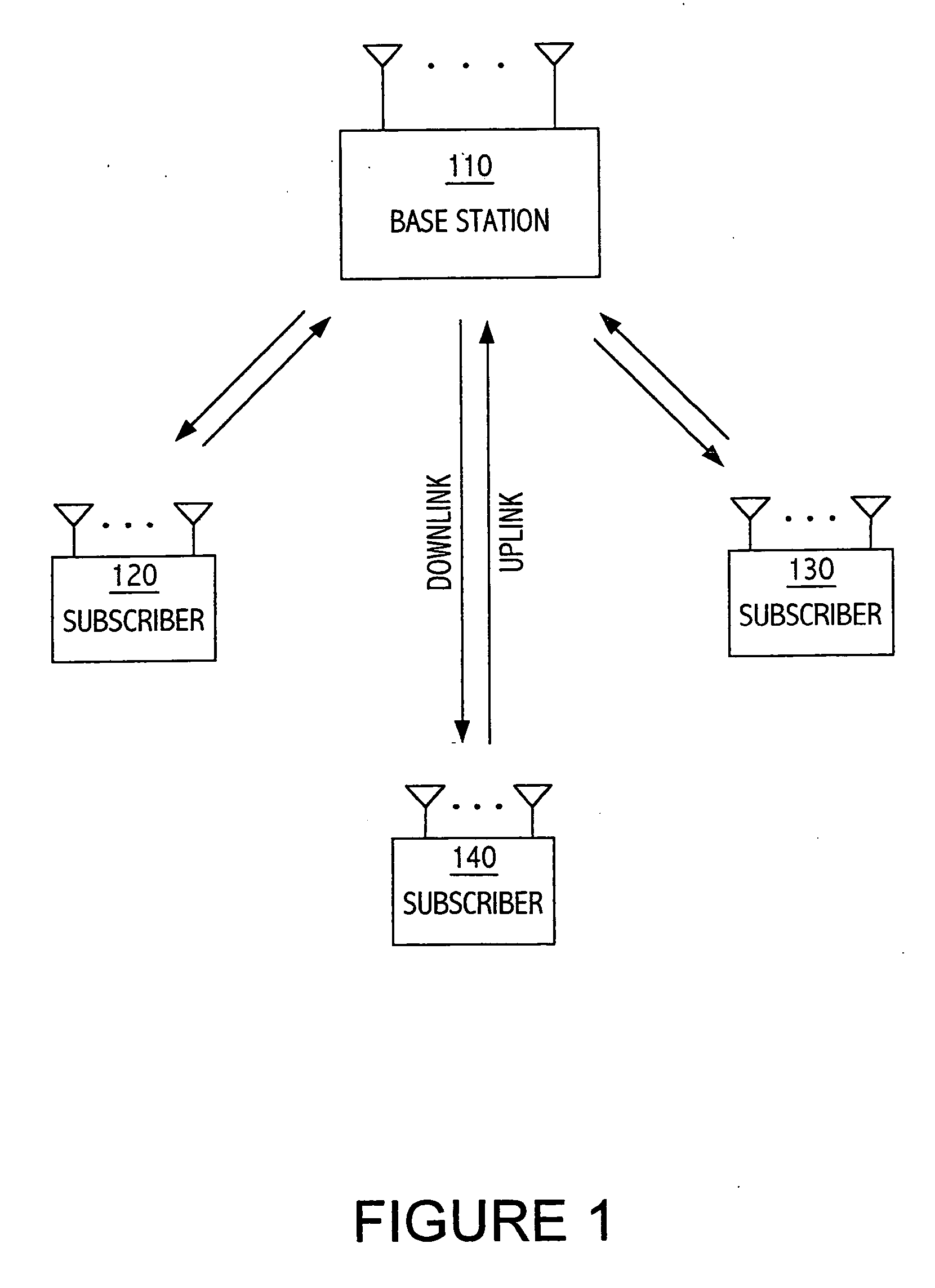
[0030] Particular embodiments of the present invention will now be described in detail with reference to the drawing figures. The techniques of the present invention may be implemented in various different types of wireless communication systems. Of particular relevance are cellular wireless communication systems, such as the system shown in FIG. 1. A base station 110 transmits downlink signals over wireless channels to multiple subscribers 120, 130, 140. In addition, the subscribers 120, 130, 140 transmit uplink signals over the wireless channels to the base station 110. Thus, for downlink communication the base station 110 is a transmitter and the subscribers 120, 130, 140 are receivers, while for ...


PUM


Abstract

The present invention includes a method of optimizing a transmission mode of wirelessly transmitted data. The method includes selecting a first transmission mode based on a predetermined channel database and a first channel characterization. The first channel characterization can be based upon signals transmitted in an initial mode. An error factor is generated based on a difference between an estimated performance characteristic, and an expected performance characteristic. A subsequent transmission mode is selected based upon the predetermined channel database, the error factor and a subsequent channel characterization. The predetermined channel database can include a predetermined look-up-table that provides transmission mode selections based upon the channel characterizations. The look-up-table generally includes a plurality of quality parameter thresholds that determine the selection of a transmission mode. Another method includes receiving transmission signals that include data encoded in an initial transmission mode. A first quality parameter of the received transmission signals is measured. A subsequent transmission mode is selected based upon the quality parameter. Transmission signals are received having data encoded in the subsequent transmission mode. A second quality parameter is measured. A parameter is adjusted within selection criteria of another subsequent transmission mode based upon the second quality parameter.

Description

RELATED APPLICATIONS [0001] This application is a continuation-in-part to application Ser. No. 09 / 665,149 filed on Sep. 19, 2000.FIELD OF THE INVENTION [0002] The invention relates generally to wireless communications between a base station and multiple users. More particularly, the invention relates to a system and method for dynamically optimizing a transmission mode of wirelessly transmitted information. BACKGROUND OF THE INVENTION [0003] Wireless communication systems commonly include information carrying modulated carrier signals that are wirelessly transmitted from a transmission source to one or more receivers within an area or region. [0004] Wireless communication systems serving stationary and mobile wireless subscribers are rapidly gaining popularity, resulting in a need for greater efficiency in the use of the available radio frequency spectrum. This goal is complicated because wireless communications channels between transmit and receive devices are inherently variable, ...

Claims


Application Information

Patent Timeline
Patent Type & Authority Applications(United States)
IPC IPC(8): H04B7/04H04J99/00H04B7/06H04B7/26H04L1/00H04L1/06H04L1/20H04L12/56H04L27/26H04W24/00H04W28/04H04W28/06
CPCH04L1/0001H04L1/0002H04L1/0003H04L1/0009H04L1/0016H04L1/0021H04W28/06H04L1/0033H04L1/06H04L1/20H04L27/2601H04W24/00H04W28/04H04L1/0026H04W28/24
Inventor CATREUX, SEVERINEGESBERT, DAVIDAIRY, MANISH
Owner APPLE INC
Learn More