Image coding method and apparatus

a coding method and image technology, applied in the field of image coding methods and apparatuses, can solve the problems of high computation cost and long processing time, inefficient truncation of code blocks, and inability to obtain the total code amount r, so as to reduce computation costs

Inactive Publication Date: 2005-05-12
CANON KK
View PDF49 Cites 42 Cited by
  • Summary
  • Abstract
  • Description
  • Claims
  • Application Information

AI Technical Summary

Benefits of technology

[0046] The present invention has been proposed to solve the conventional problems, and has as its object to provide an image coding method and apparatus which can properly reduce the computation cost required for rate / distortion optimization processing in image coding at the time of image compression.

Problems solved by technology

At truncatable point 2, the rate / distortion gradient does not monotonously reduce, and hence it is not efficient to truncate a code of the code block.
Therefore, for example, a high computation cost and long processing time are required to obtain the total code amount R because this processing is performed by, for example, accessing the memory storing the code truncation candidate point information Si(k) and Ri(k) many times and comparing si(k) with λ.
Furthermore, there is no known method of performing rate / distortion optimization processing for moving images at high speed.

Method used


Image

  • Image coding method and apparatus
  • Image coding method and apparatus
  • Image coding method and apparatus

Examples


first embodiment

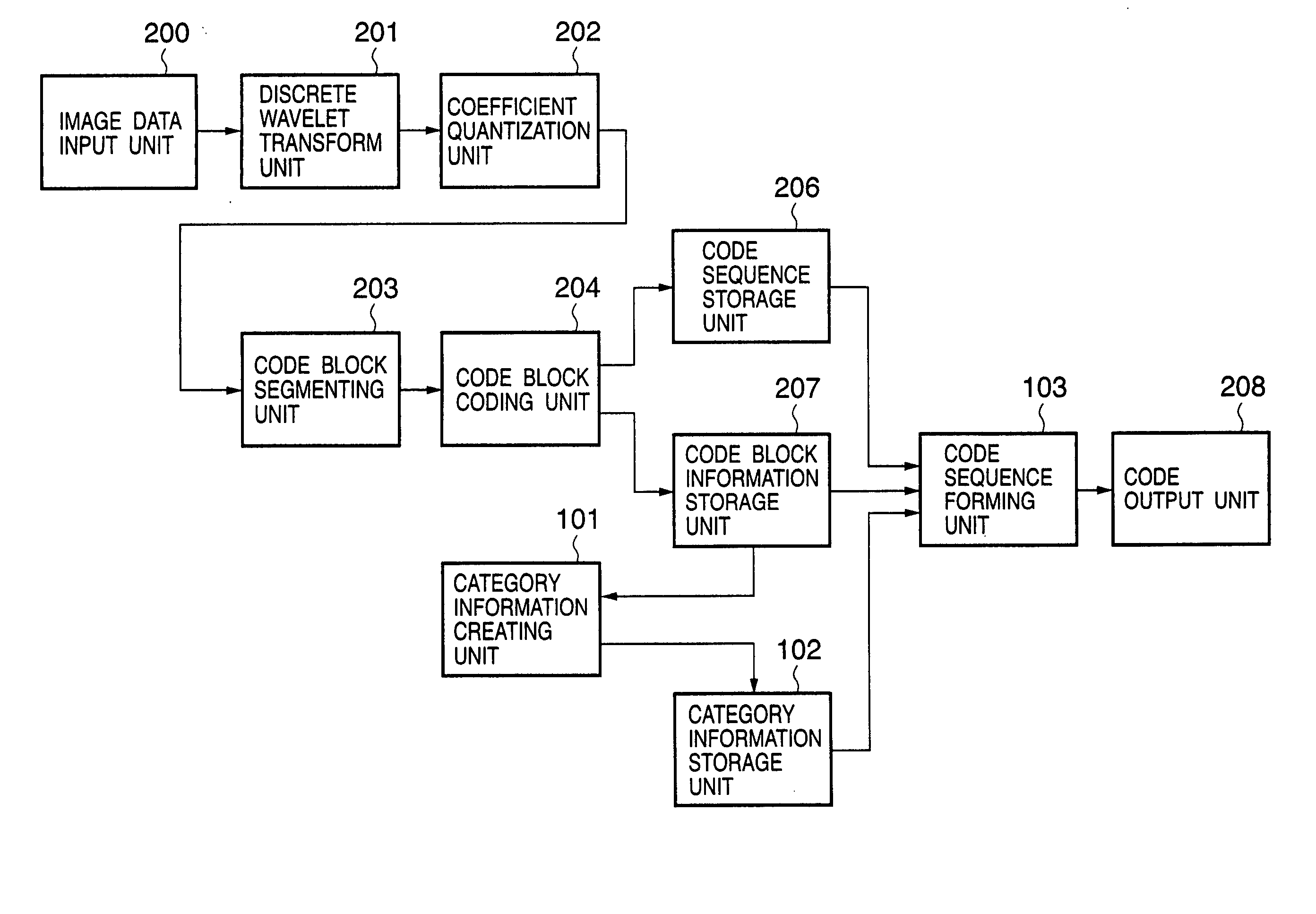
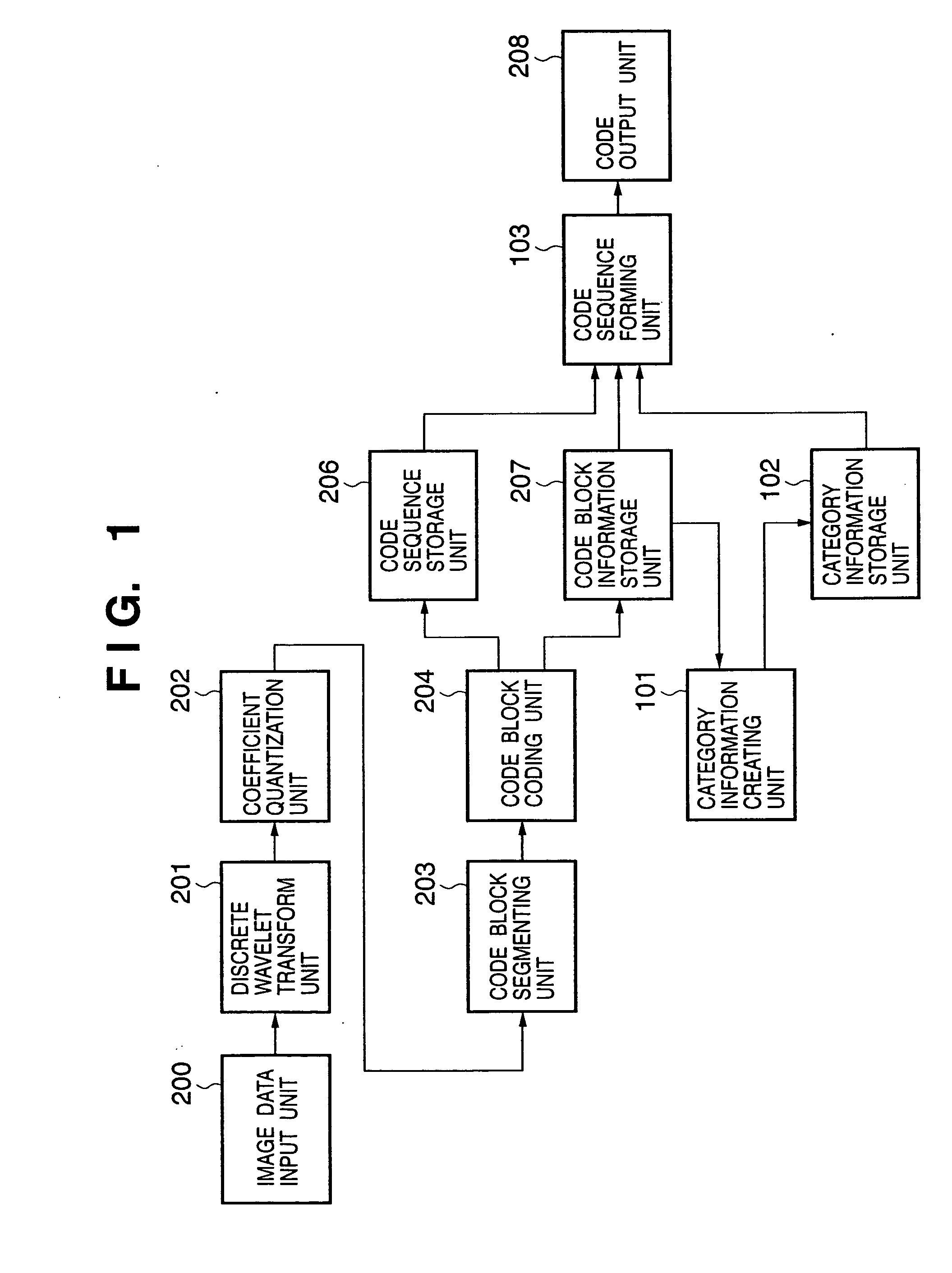
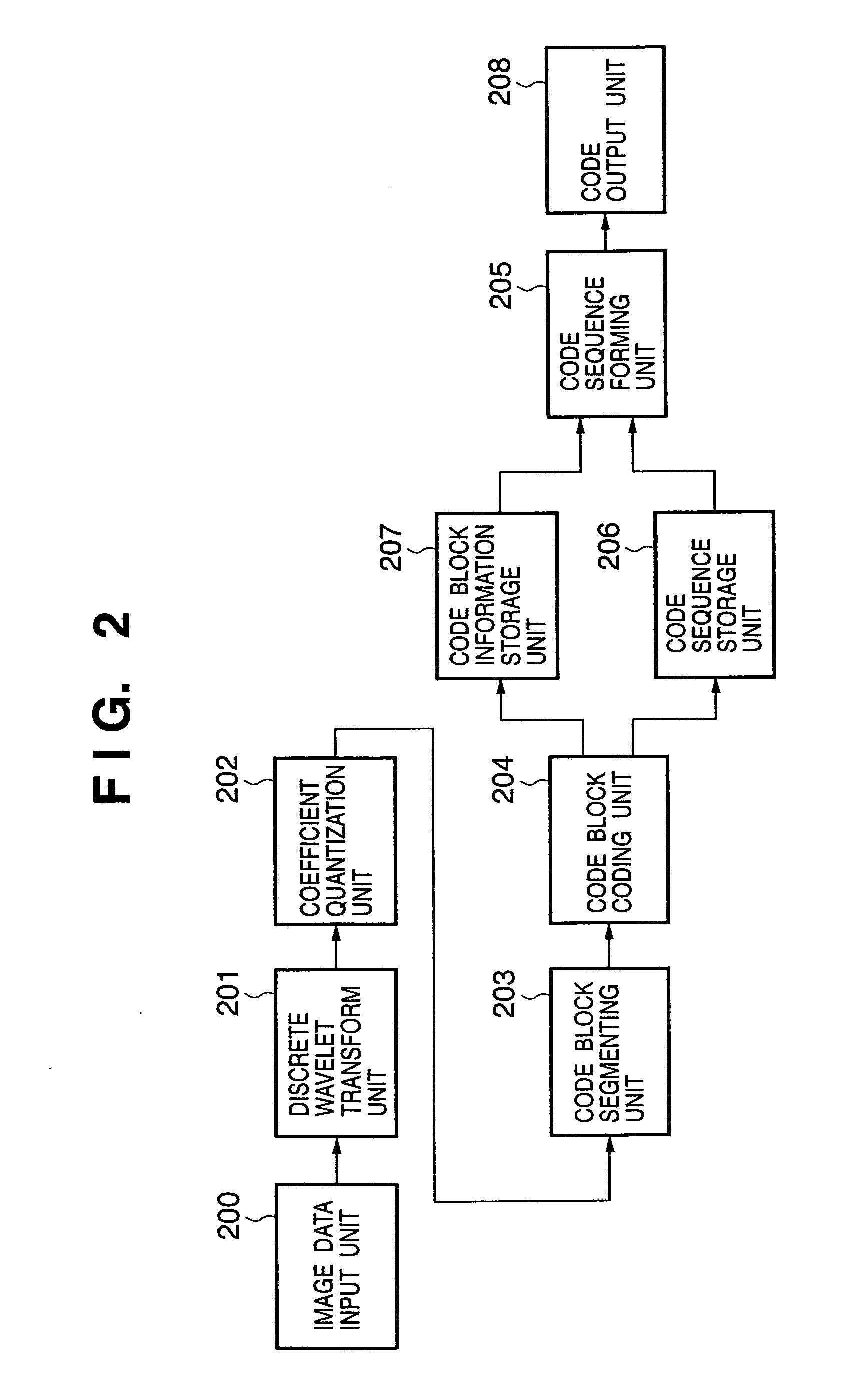
[0149]FIG. 1 is a block diagram showing the arrangement of an image coding apparatus according to the first embodiment of the present invention. The same reference numerals as in FIG. 1 denote blocks common to the conventional image coding apparatus shown in FIG. 2 described above, and a description thereof will be omitted. As shown in FIG. 1, the image coding apparatus according to the first embodiment includes an image data input unit 200, discrete wavelet transform unit 201, coefficient quantization unit 202, code block segmenting unit 203, code block coding unit 204, code sequence forming unit 103, code block information storage unit 207, code sequence storage unit 206, category information creating unit 101, category information storage unit 102, and code output unit 208.

[0150] An example of the operation of the image coding apparatus according to the first embodiment will be described below with reference to FIG. 1. Note that image coding data to be coded by the image coding ...

second embodiment

[0165] In the image coding apparatus according to the first embodiment described above, rate / distortion optimization processing is simplified by holding a cumulative code amount for each code amount (rate) / distortion gradient category, and searching for a threshold inside a category (boundary category) including a target code amount. In this case, if sufficiently fine classification is performed by increasing the category count or a slight deterioration in performance is permitted, threshold search processing inside a boundary category can be omitted. The second embodiment will exemplify the coding processing performed by the image coding apparatus designed to make no threshold search inside a boundary category.

[0166] The image coding apparatus according to this embodiment differs from the image coding apparatus described with reference to FIG. 1 in the first embodiment only in the processing by the code sequence forming unit 103, and the remaining arrangement is the same as that o...

third embodiment

[0173] The image coding apparatus according to the first embodiment described above is designed to simplify rate / distortion optimization processing by holding a cumulative code amount for each rate / distortion category, and searching for a threshold inside a category (boundary category) including a target code amount. That is, in threshold search processing inside a boundary category, a search for a threshold corresponding to a target code amount is made while a threshold is changed little by little. In contrast to this, the third embodiment will exemplify a case wherein a threshold search is made more efficiently by estimating a threshold λ from the information of a boundary category and an immediately preceding category (one level higher in priority).

[0174] The image coding apparatus according to this embodiment differs from the image coding apparatus described with reference to FIG. 1 in the first embodiment only in the processing by the code sequence forming unit 103, and the re...


PUM


Abstract

There are provided an image coding method and apparatus which can properly reduce the computation cost required for rate/distortion optimization processing in image coding at the time of image compression. First of all, the rate/distortion gradient of a frame of interest is classified to m categories. A category information creating unit (101) acquires a threshold λ for a preceding frame from a predictive value storage unit (104) as a predictive value λ′ for the frame of interest when the frame of interest is to be coded, and further finely segments a category in which the predictive value λ′ is included. A code amount is then calculated for each of n categories in which the predictive value λ′ is included. A code sequence forming unit (103) selects a category having a target rate, and searches for a threshold between an upper limit value Tn(x-1) and lower limit value Tn(x) of the category. S at the end of the processing is selected as the threshold λ, and a code sequence is formed by using the threshold λ.

Description

FIELD OF THE INVENTION [0001] The present invention relates to an image coding method and apparatus which code still images or frame images of moving images. BACKGROUND OF THE INVENTION [0002] As a technique of improving image coding efficiency, a code amount (rate) / distortion optimization technique is available. The rate / distortion optimization technique is designed to obtain a generated code amount and an index value associated with image distortion for each of a plurality of sections constituting coded data and minimize the total distortion index value under the condition that the total code amount is equal to or less than a target value. [0003] According to international standard JPEG2000 (ISO / IEC 15444) for still image coding established by standardization in ISO / IEC JTC1 / SC29 / WG1, the coefficient of each subband obtained by wavelet transform is segmented into rectangular regions called code blocks, and each rectangular region is independently coded. JPEG2000 codes each code bl...

Claims


Application Information

Patent Timeline
Patent Type & Authority Applications(United States)
IPC IPC(8): G06K9/36H04N7/26
CPCH04N19/176H04N19/147H04N19/647H04N19/63H04N19/192H04N19/132H04N19/146H04N19/19H04N19/115
Inventor KAJIWARA, HIROSHIKISHI, HIROKI
Owner CANON KK
Why Eureka
Try Eureka