Device for an injector

a technology of injectors and devices, applied in the field of injectors, can solve the problems of complicated devices and unusable users, and achieve the effect of high functionality and convenient us

Inactive Publication Date: 2005-05-12
SHL MEDICAL
View PDF5 Cites 333 Cited by
  • Summary
  • Abstract
  • Description
  • Claims
  • Application Information

AI Technical Summary

Benefits of technology

[0006] The aim of the invention is to provide an injection device which is uncomplicated and easy to use, which is safe both before, during and after use and which displays a high degree of functionality.
[0012] The axial movement in order to release the holding means is thus performed both by the actuator sleeve but also by the holding means. There is thus a two-step operation in order to activate an injection. For enhancing the safety of the device it is designed so that the operation of the device is performed in a pre-determined sequence.
[0015] The mechanism of the injector of the present invention is designed such that an injection is only activated when first the injector is pressed against the injection site and then the activator (e.g. a button) is pressed or activated. It is not possible to press the activator first and then press the injector against an object to activate an injection nor is it possible to perform these steps simultaneously. Also if the injector is removed from an injection site before the activator is pressed, the injector is reset to its original locked state. This ensures a very high degree of safety in handling the device and prevention of faulty or not performed injections.

Problems solved by technology

The handling and safety aspects of injector devices, having a certain degree of automatic functions, as well as immediate accessibility in emergency situations are issues that attract a lot of attention when developing this type of device.
However many of these solutions are rather bulky and rely also on many components acting in co-operation and in sequence, one trigging another, which may lead to a mal-function, or that the device becomes complicated, hence not user friendly.

Method used


Image

  • Device for an injector
  • Device for an injector
  • Device for an injector

Examples


Embodiment Construction

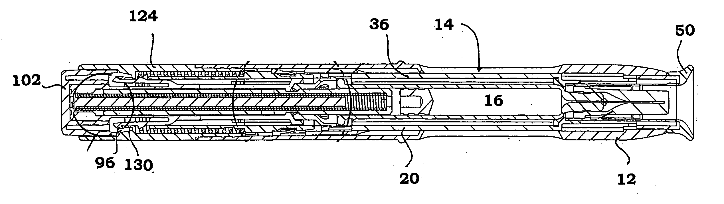
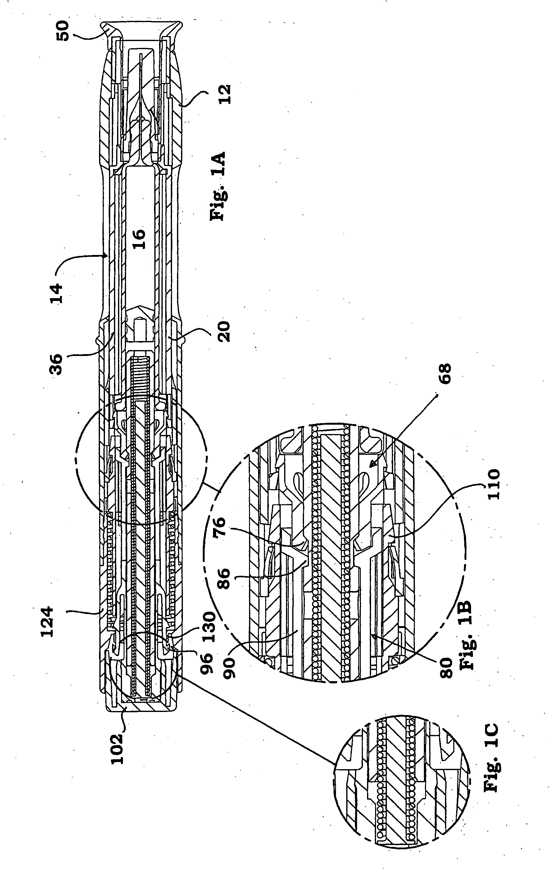
[0039] The embodiment shown in the drawings comprises a front part 10, FIGS. 2-3 and a rear part 60, FIGS. 4-5.

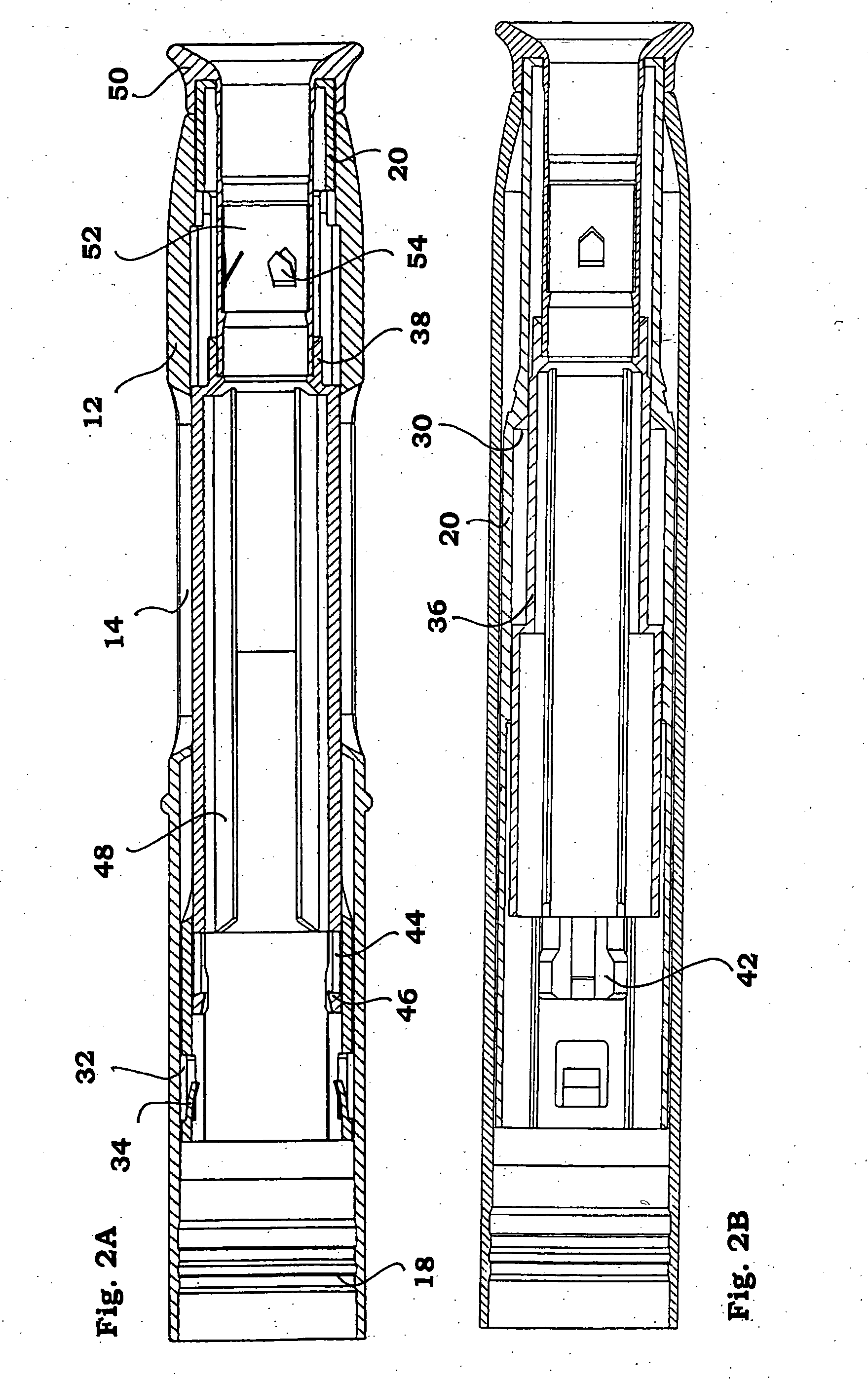
[0040] The front part 10 comprises a generally tubular front body 12 having elongated openings 14 for viewing a syringe 16, FIG. 1, and a somewhat narrowing front end. The rear end is arranged with annular recesses 18 on the inner surface. Inside the front body a needle shield 20 is slidably arranged. The needle shield is generally tubular with a first front part 22 having a certain diameter and a second rear part 24 having a diameter larger than the front part, where these parts are joined by an intermediate conical part 26, FIG. 3. Two elongated grooves 28 are arranged along the needle shield, on opposite sides of the needle shield, also for viewing the syringe. On the inner surface of the conical part a circumferential ledge 30 is arranged. At the rear end of the needle shield two openings 32 are arranged opposite each other, where each opening is arranged with somewhat...


PUM


Abstract

The present invention relates to an injection device comprising a generally elongated tubular housing, a syringe containing medicament and having a needle, a needle shield slidably arranged to the housing and protruding a distance outside the front end of the housing, a plunger arranged to act on the syringe and a pre-tensioned drive member arranged the drive the plunger, characterized in that it comprises radially acting holding elements capable of releasably holding the plunger, axially acting actuator elements connected to the needle shield and capable of releasably locking the holding elements and axially acting activator elements capable of releasing the holding elements from the actuator elements have when the needle shield and the actuator elements has moved axially a certain distance due to that injection device has been placed against an injection site.

Description

TECHNICAL FIELD [0001] The present invention relates to an injector for administering drugs in a safe and reliable way. BACKGROUND OF THE INVENTION [0002] The handling and safety aspects of injector devices, having a certain degree of automatic functions, as well as immediate accessibility in emergency situations are issues that attract a lot of attention when developing this type of device. [0003] A few of these devices have safety aspects like a two-step operation before the injection is activated in order to avoid unintended activation, for example if the user comes in contact with the trigger button before the injector is placed at the injection site. However many of these solutions are rather bulky and rely also on many components acting in co-operation and in sequence, one trigging another, which may lead to a mal-function, or that the device becomes complicated, hence not user friendly. [0004] One device utilising a high degree of automation is described in the document WO 02...

Claims


Application Information

Patent Timeline
Patent Type & Authority Applications(United States)
IPC IPC(8): A61M5/20A61M5/32
CPCA61M5/2033A61M5/326A61M2005/208A61M2005/206A61M2005/2013A61M5/3204
Inventor BRUNNBERG, LENNART
Owner SHL MEDICAL
Why Eureka
Try Eureka