Hinge for portable terminal

a portable terminal and hinge technology, applied in the direction of hinges, manufacturing tools, wing accessories, etc., can solve the problems of monotonous operation, difficult to produce strength, complicated functions expected of the opening/closing hinge, etc., and achieve the effect of preventing malfunctions

Inactive Publication Date: 2005-05-19
KATOH ELECTRIC MACHINERY
View PDF8 Cites 22 Cited by
  • Summary
  • Abstract
  • Description
  • Claims
  • Application Information

AI Technical Summary

Benefits of technology

[0011] Since the second hinge shaft to which the second member is attached is crossed and engaged with the first hinge shaft and is constructed to be capable of rotating only at a predetermined rotation angle of the first hinge shaft, it is possible to prevent displacement of the second hinge shaft and the first hinge shaft in the axial direction even when the first member and the second member are repeatedly opened and closed, so that the positional displacement does not occur and malfunctions can be prevented. Moreover, when the first member and the second member are opened / closed, the cam portion of the cam follower is in pressure contact with the respective cam portions of the inner cam and the outer cam which are overlapping with each other, so that an advantage can be achieved that the opening operation and the closing operation can be varied to provide opening / closing operations with different senses of operations respectively.

Problems solved by technology

Also, in recent years, various functions (camera function for example) are added to cellular phones, so that, along with such addition, functions expected from an opening / closing hinge are complicated as well.
Thus, there has been a problem that a force to pull the receiver section away from the transmitter section in an up and down direction is generated at the time of opening / closing, which causes positional displacement in a left and right direction to cause a malfunction.
Further, the conventionally known one has problems such that it is difficult to produce strength in the hinge, and that the sense of operation is monotonous since opening / closing operations in the opening direction and the closing direction are the same.

Method used


Image

  • Hinge for portable terminal
  • Hinge for portable terminal
  • Hinge for portable terminal

Examples


Embodiment Construction

[0041] Hereinafter, an embodiment of the present invention will be described based on the drawings.

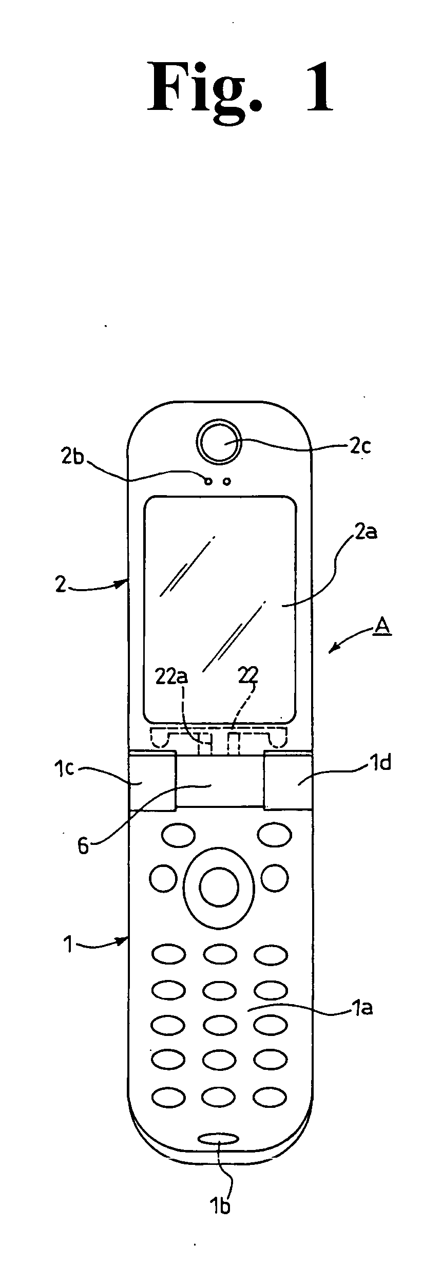
[0042] In FIG. 1, the reference numeral 1 denotes a transmitter section constituting a first member of a cellular phone A of two-fold type, and on its top surface side, a keyboard 1a and a microphone 1b are provided. The reference numeral 2 denotes a receiver section constituting a second member, and on a side thereof facing the keyboard side when it is closed, a display portion 2a, a speaker 2b, and a camera 2c are provided.

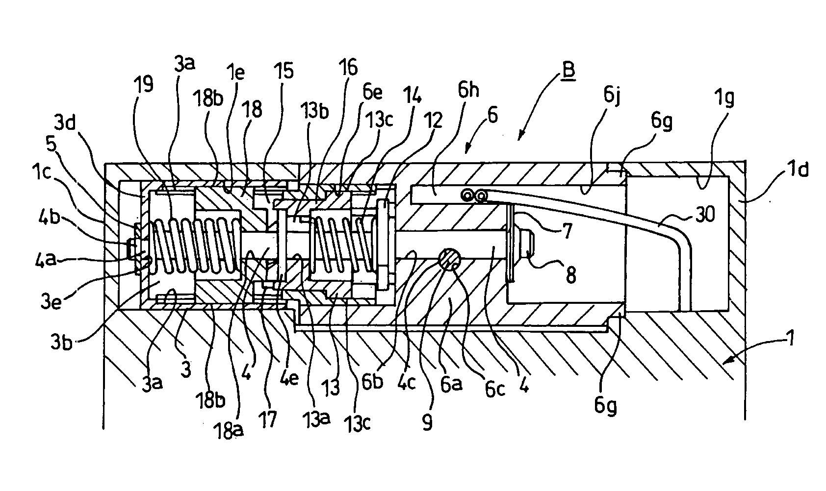
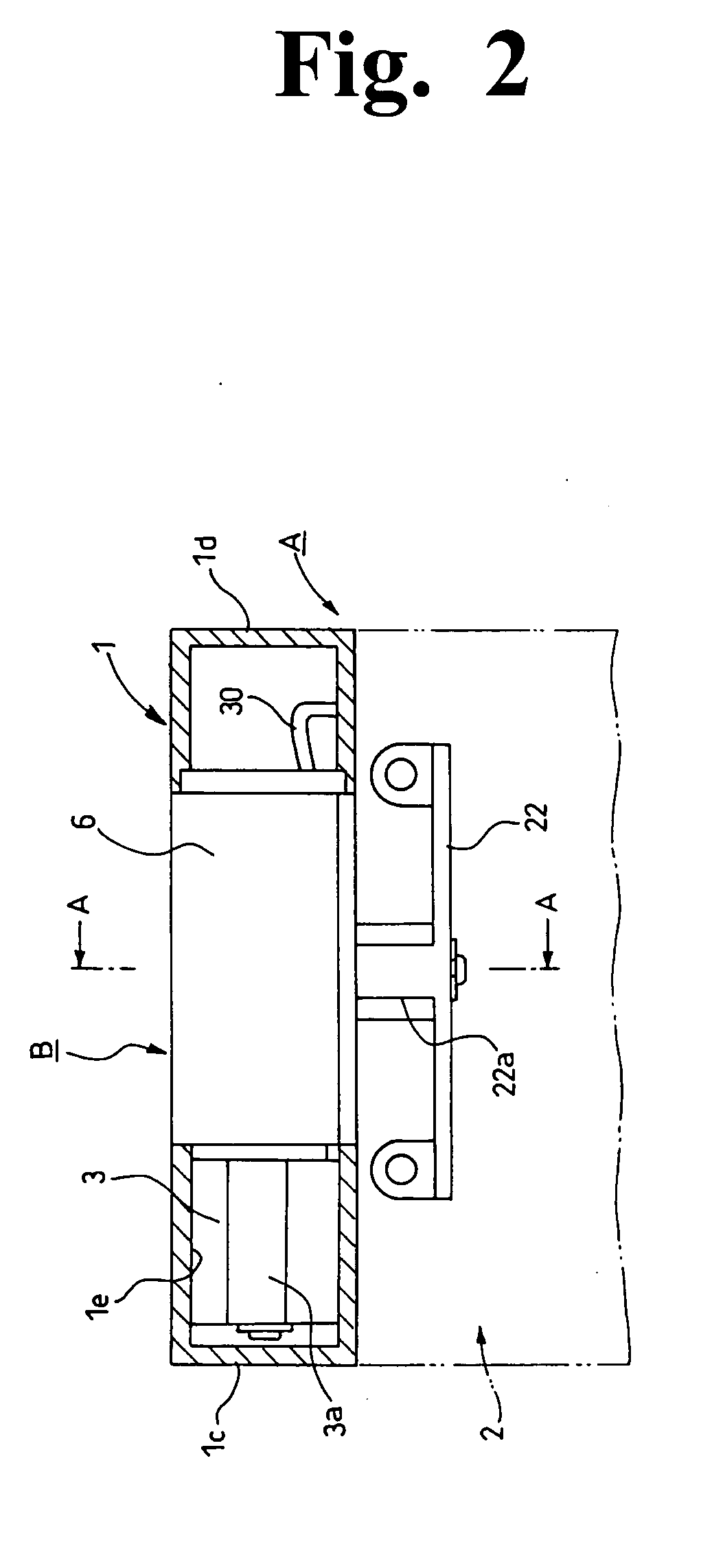
[0043] A hinge B according to the present invention is, as shown particularly in FIG. 1, attached between attaching portions 1c, 1d for coupling the transmitter section 1, and the structure thereof is shown in FIG. 2 to FIG. 20.

[0044] According to the drawings, as shown particularly in FIG. 5, one shown by the reference numeral 3 and located on the left side is a cylindrical case whose one end is open. As shown particularly in FIG. 8 and FIG. 15, this case 3 has...


PUM


Abstract

A portable terminal hinge prevents positional displacement of components, precludes malfunctions and performs a different operation when opening and closing. A first member of the hinge has a keyboard and is coupled to a second member having a display for the terminal. The members are capable of opening/closing in a vertical direction and of rotating in a horizontal direction at a predetermined open angle. The hinge includes a first hinge shaft coupling the members for opening/closing in the vertical direction and a second hinge shaft coupling the members for rotating in the horizontal direction. The first and second hinge shafts are crossed and engaged with each other so that the second hinge shaft is capable of rotating only at a predetermined rotation angle of the first hinge shaft accompanying the opening/closing operation in the vertical direction.

Description

FIELD AND BACKGROUND OF THE INVENTION [0001] The present invention relates to a hinge for portable terminal suitable for use in portable terminals such as a cellular phone, a small-sized office automation device, and the like. DESCRIPTION OF THE RELATED ART [0002] Regarding cellular phones among other portable terminals, for the reasons of portability, protection of a keyboard surface, prevention of malfunctions, and the like, two-fold types in which a transmitter section that is a first member and a receiver section that is a second member are coupled together to each other via a hinge are becoming the mainstream. Also, in recent years, various functions (camera function for example) are added to cellular phones, so that, along with such addition, functions expected from an opening / closing hinge are complicated as well. [0003] In such a situation, a hinge constructed such that a transmitter section and a receiver section can be opened / closed using two shafts and further the receive...

Claims


Application Information

Patent Timeline
Patent Type & Authority Applications(United States)
IPC IPC(8): F16C11/04E05D3/10E05D11/08E05D11/10E05F1/12H04B1/38H04M1/02
CPCE05D3/10E05D11/087E05D11/1078E05F1/1215Y10T16/540255H04M1/0212Y10T16/5472Y10T16/547E05Y2900/606H04B1/38
Inventor KATO, HIDEO
Owner KATOH ELECTRIC MACHINERY
Why Eureka
Try Eureka