Support Shoe for Concrete Pylons

a technology for supporting shoes and concrete pylons, which is applied in the direction of machine supports, furniture parts, other domestic objects, etc., can solve the problems of difficult welding, difficult positioning of welding seams, and difficulty in reliable welding of reinforcement bars to the two legs, so as to improve the accessibility of screw connections, facilitate welding, and facilitate welding. the effect of the carrying capacity

Inactive Publication Date: 2005-05-19
LEVIAT GMBH
View PDF22 Cites 29 Cited by
  • Summary
  • Abstract
  • Description
  • Claims
  • Application Information

AI Technical Summary

Benefits of technology

[0015] In an advantageous embodiment, the lateral plate has a longitudinal slot in which the reinforcement bar is secured, respectively. In this way, the reinforcement bar is positioned at least approximately within the sheet plane; this leads to a central force introduction that increases the carrying capacity. In this connection, the two reinforcement bars have a comparatively large distance relative to one another. This contributes, particularly in combination with shortened lateral plates, to an improved accessibility of the screw connection as well as a simplified positional tolerance compensation of two base plates resting against one another. A reliable and easily controllable welding action is possible from the inner side as well as the outer side of the respective lateral plate. Welding of the reinforcement bar or of an appropriate threaded sleeve for receiving a reinforcement bar can be realized without spatial restriction of a quality control.
[0016] In an advantageous variant, the edges of the two lateral plates that are spaced from the base plate are connected in the area of their upper ends to a transverse plate wherein one or several reinforcement bars are secured to the transverse plate. By means of the transverse plate, the reinforcement bars can be secured in close proximity to the hole axis of the screw hole. In this way, a correspondingly beneficial course of the force within the concrete part is realized without the accessibility of the screw connection being limited by the reinforcement bars.
[0017] A variant may also be advantageous in which the reinforcement bars are welded to the respective outer side of the lateral plates. This enables easy accessibility of the welding seams.
[0018] Optionally, an embodiment may be expedient where the vertical edges of the lateral plates that are spaced apart from one another extend at a slant to the rear away from the base plate. This provides a wider lower area of the lateral plates that enables a sturdily sized welding connection to the base plate. As a result of the vertical edge extending at a slant to the rear, the lateral plates become narrower with increasing spacing from the base plate; this increases the movement space of a screwing tool to be used.

Problems solved by technology

Tolerances resulting from folding of the lateral sheet metal can lead to difficulties when welding them to the base plate.
A reliable welding of the reinforcement bars to the two legs is made more difficult because the accessibility of the welding seams positioned in the direction of the fold line is impaired by the lateral plates.
The accessibility of the screw connection as well as a positional tolerance compensation of two adjoining screw holes relative to one another are made more difficult.

Method used


Image

  • Support Shoe for Concrete Pylons
  • Support Shoe for Concrete Pylons
  • Support Shoe for Concrete Pylons

Examples


Embodiment Construction

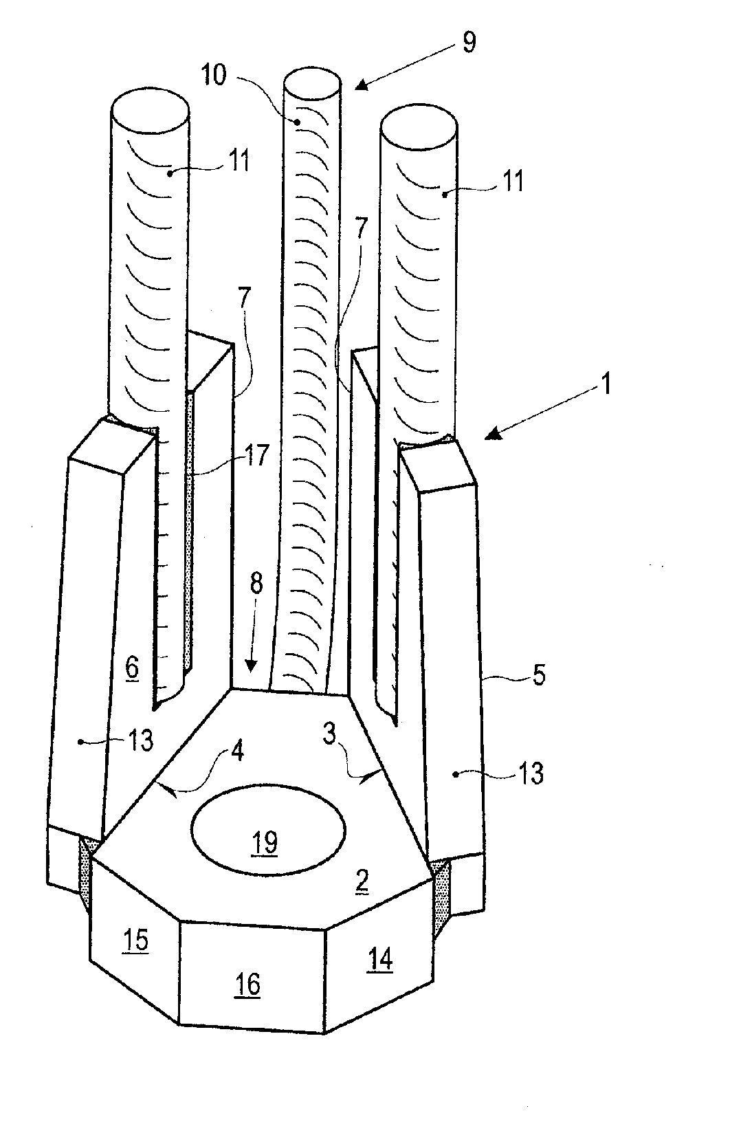
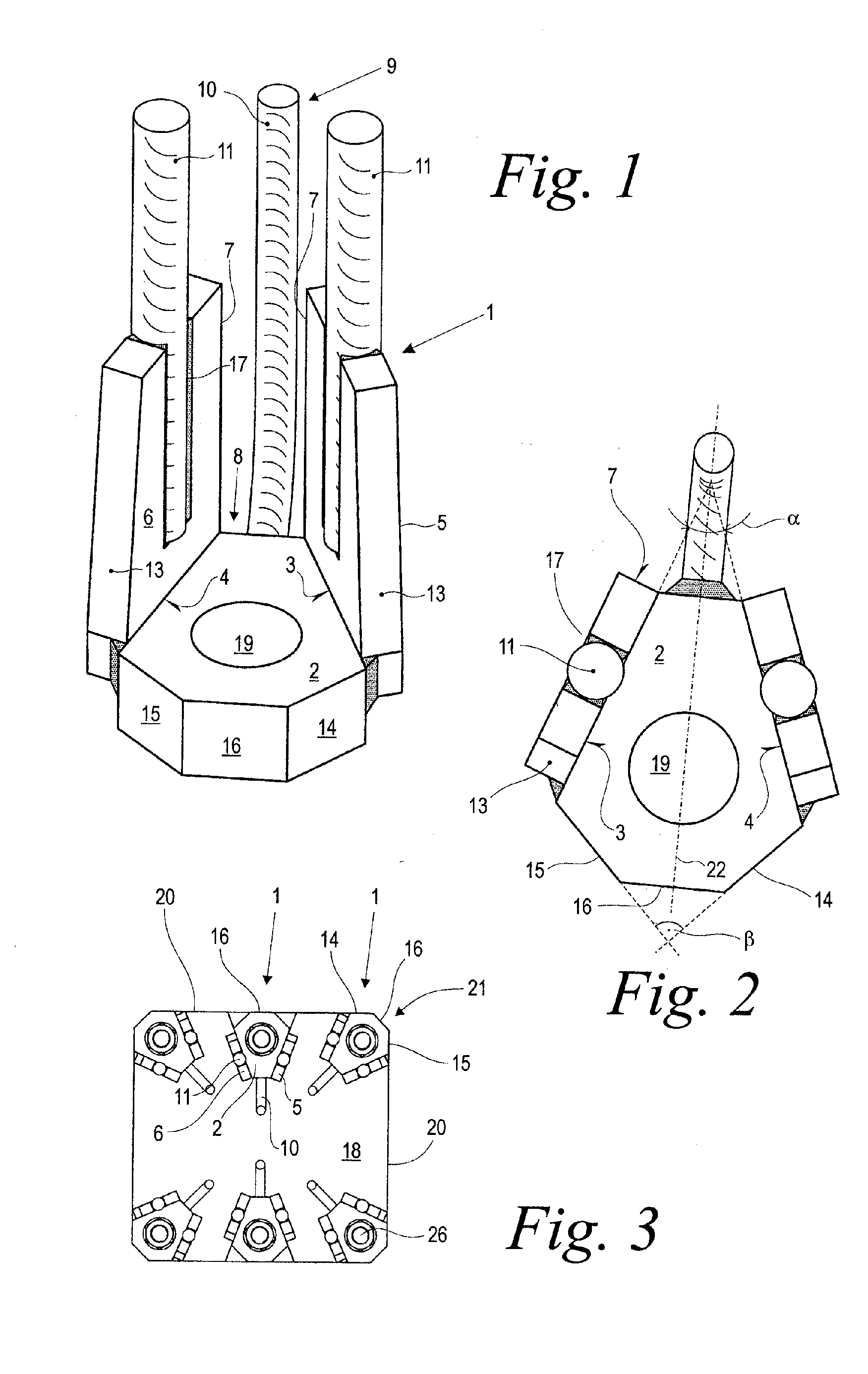
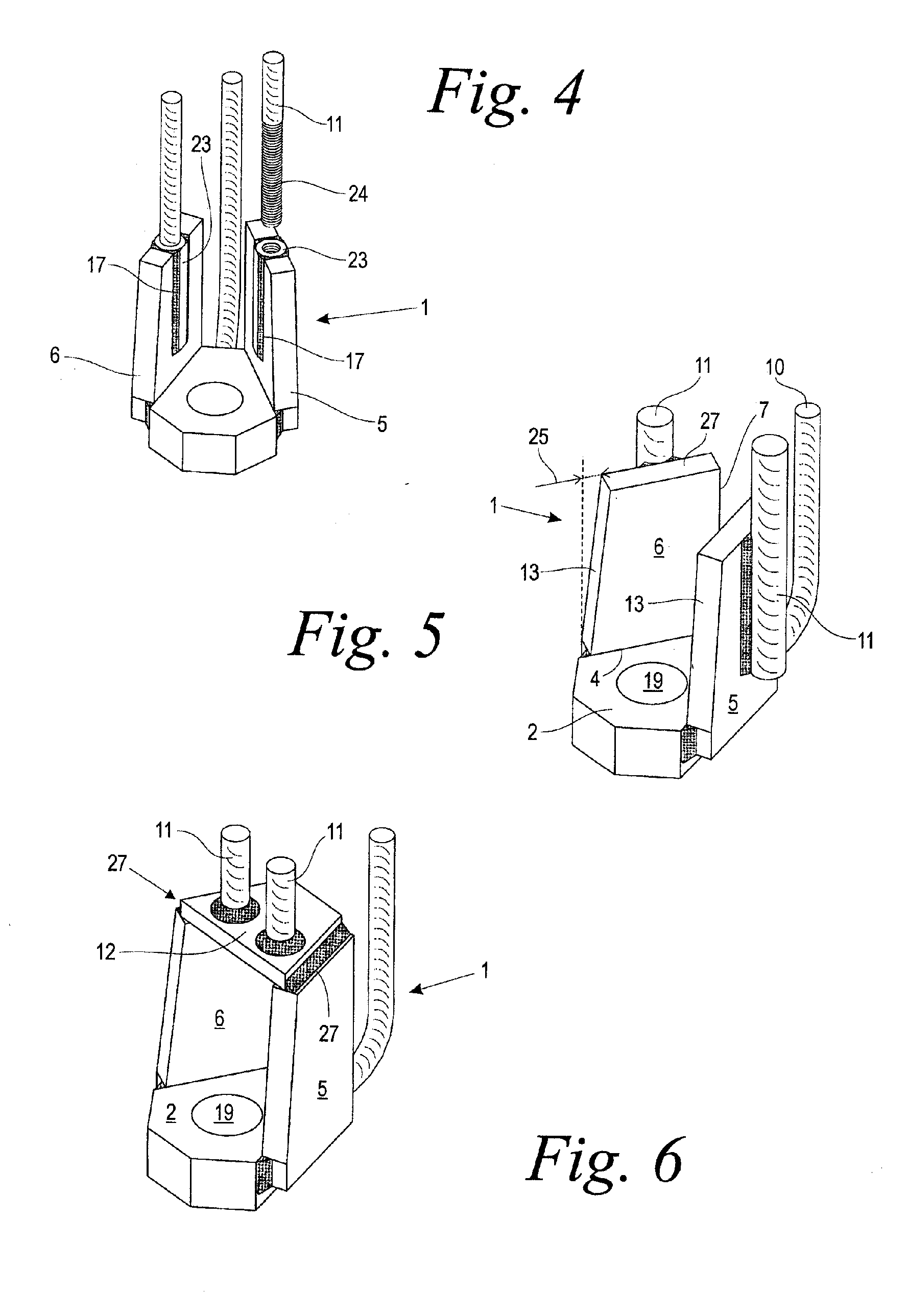
[0026]FIG. 1 shows in a perspective front view a support shoe 1 comprising a base plate 2, two lateral plates 5, 6, as well as reinforcement bars 10, 11. In the illustrated embodiment, the base plate 2 has a polygonal footprint formed by a front edge 16, two corner edges 14, 15, two lateral edges 3, 4 adjoining the corner edges, and a rear transverse edge 8. The base plate 2, relative to its extension in the transverse direction, is provided with a centrally arranged opening 19 for receiving a fastening means.

[0027] The two lateral plates 5, 6 extend at a right angle to the base plate 2 and are welded to the two lateral edges 3, 4 of the base plate 2. The two lateral plates 5, 6 have each a longitudinal slot 17 extending in the vertical direction and receiving a reinforcement bar 11, respectively. In the illustrated embodiment, the reinforcement bars 11 are secured by welding in the longitudinal slots 17 so that they extend in the plane of the lateral plates 5, 6. The reinforcement...


PUM


Abstract

A support shoe for a concrete pillar has a base plate and two lateral plates arranged at lateral edges of the base plate and projecting upwardly at a right angle from the base plate. At least one reinforcement bar is connected to the support shoe for introducing forces into the concrete pillar. The two lateral edges and thus also the lateral plates connected thereto are arranged at an acute angle relative to one another, wherein the two lateral plates are formed as separate components connected to the base plate.

Description

BACKGROUND OF THE INVENTION [0001] The invention relates to a support shoe for concrete supports or pylons, concrete pillars or the like. The support shoe comprises a base plate and two lateral plates arranged at lateral edges of the base plate and projecting approximately at a right angle upwardly from the base plate and comprising at least one reinforcement bar that is connected to the support shoe for introducing forces into the concrete pillar. [0002] Such support shoes are used, for example, in high-rise construction for connecting by screwing pre-manufactured concrete parts. For example, appropriately pre-manufactured concrete pillars have in the area of their end faces several support shoes that are fixedly embedded in the concrete part together with reinforcement bars secured on lateral plates of the support shoe. A base plate and lateral plates that are arranged on lateral edges of the base plate at a right angle relative to the base plate delimit a free space that enables ...

Claims


Application Information

Patent Timeline
Patent Type & Authority Applications(United States)
IPC IPC(8): E02D5/52E04B1/21
CPCE04B1/215E02D5/523
Inventor FROHLICH, KLAUSHANKE, ANDREAS
Owner LEVIAT GMBH
Why Eureka
Try Eureka