Unlock instant, AI-driven research and patent intelligence for your innovation.

Bicycle pedal

Inactive Publication Date: 2005-05-19
SHIMANO INC
View PDF23 Cites 0 Cited by
  • Summary
  • Abstract
  • Description
  • Claims
  • Application Information

AI Technical Summary

Benefits of technology

[0012] One object of the present invention is to provide a bicycle pedal that is configured and arranged such the rider can easily step into engagement with the clamping members.
[0013] Another object of the present invention is to provide a step-in bicycle pedal that is relatively lightweight and malfunction free.
[0014] Yet another object of the present invention is to provide a step-in bicycle pedal that is relatively simple and inexpensive to manufacture.

Problems solved by technology

However, the bicycle pedal is often not in a horizontal position in which the rider can easily step into engagement with the clamping members.
Due to the unique construction of the bicycle pedals, the rider some times has a hard time rotating the pedal from a non-horizontal position to a substantially horizontal position.
Some of these prior step-in or clipless pedals can inadvertently release the cleat during normal pedaling if the spring force on the rear clamping member is set too low.
However, if the spring force on the rear clamping member is set too high, the cleat may not release from the pedal properly.
This could result in the rider's shoe not properly releasing from the pedal at the desired application of force because the rider's shoe either releases too easily from the pedal or does not release at the proper time.
However, these adjustment mechanisms increase the overall cost of the pedals.
In particular, these adjustment mechanisms can be complicated and expensive to manufacture and assemble.

Method used


Image

  • Bicycle pedal
  • Bicycle pedal
  • Bicycle pedal

Examples


Embodiment Construction

[0061] Selected embodiments of the present invention will now be explained with reference to the drawings. It will be apparent to those skilled in the art from this disclosure that the following descriptions of the embodiments of the present invention are provided for illustration only and not for the purpose of limiting the invention as defined by the appended claims and their equivalents.

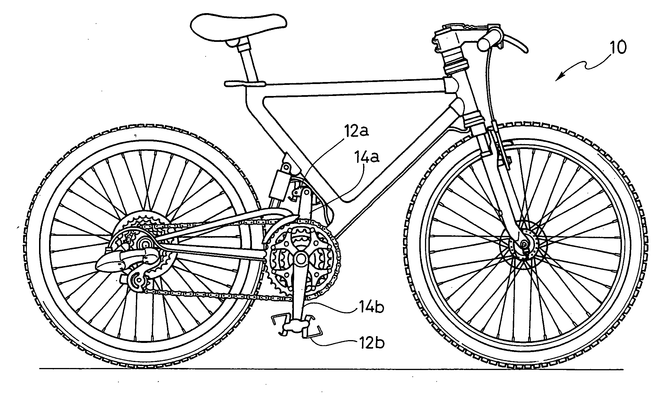
[0062] Referring initially to FIG. 1, a bicycle 10 is illustrated that is equipped with a left bicycle pedal 12a and a right bicycle pedal 12b in accordance with a first embodiment of the present invention. The bicycle pedals 12a and 12b are fixedly coupled to a pair of bicycle crank arms 14a and 14b of a bicycle 10 for rotation therewith.

[0063] As seen in FIGS. 2-5, the left and right bicycle pedals 12a and 12b selectively engage a pair of cleats A and B. Thus, the left and right bicycle pedals 12a and 12b and the cleats A and B that are form a bicycle pedal assembly in accordance with a first ...


PUM


Abstract

A bicycle pedal has a body with at least one pair of clamping members that are pivotally coupled to the pedal body. The rear clamping member pivots through a predetermined angle that is larger than the predetermined angle of pivot of the front clamping member for easy entry of the cleat. Each clamping member has a cleat stop surface with the front cleat stop surface being spaced farther from the center rotational axis than the rear cleat stop surface for easy entry of the cleat. Each clamping member has a cleat engagement surface with the front cleat engagement surface being radially spaced from its pivot axis by a distance that is less than the radially spacing of the rear cleat engagement surface being spaced from its pivot axis. The rear clamping member has an elongated tongue extending past the pedal body end to allow the rider to rotate the pedal.

Description

CROSS-REFERENCE TO RELATED APPLICATIONS [0001] This application is a divisional application of U.S. patent application Ser. No. ______ (Attorney File No. SN-US035146) filed on Nov. 14, 2003. The entire disclosure of U.S. patent application Ser. No. ______ (Attorney File No. SN-US035146) is hereby incorporated herein by reference.BACKGROUND OF THE INVENTION [0002] 1. Field of the Invention [0003] This invention generally relates to a bicycle pedal. More specifically, the present invention relates clipless or step-in bicycle pedal, which is configured to engage a cleat that is coupled to a bicycle shoe. [0004] 2. Background Information [0005] Bicycling is becoming an increasingly more popular form of recreation as well as a means of transportation. Moreover, bicycling has become a very popular competitive sport for both amateurs and professionals. Whether the bicycle is used for recreation, transportation or competition, the bicycle industry is constantly improving the various compone...

Claims


Application Information

Patent Timeline
IPC IPC(8): B62M3/08
CPCY10T74/217B62M3/086
Inventor MURAOKA, TSUTOMU
Owner SHIMANO INC