
Inflatable multi-function parabolic reflector apparatus and methods of manufacture

a parabolic reflector and multi-function technology, applied in the direction of mirrors, solar heat collector controllers, energy-based wastewater treatment, etc., can solve the problems of plurality of losses, total of six significant transmission losses, and significant limitations in all related art, so as to enhance the transmission or reception of radio signals and enhance vision

Inactive Publication Date: 2005-05-19
ESSIG JOHN R JR +1
View PDF43 Cites 31 Cited by
  • Summary
  • Abstract
  • Description
  • Claims
  • Application Information

AI Technical Summary

Benefits of technology

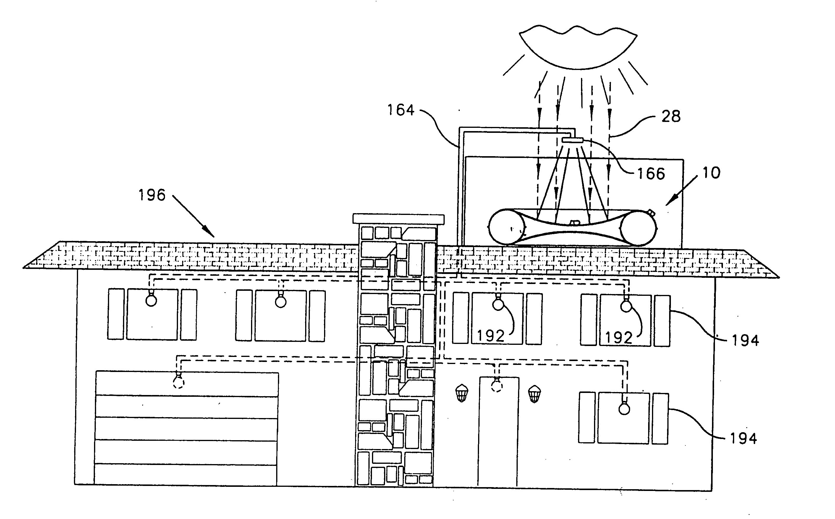
[0042] The invention, in its preferred embodiments, is a portable, multifunction, multipurpose, inflatable parabolic reflector device (apparatus) made from pressure-deformable membranes, of which at least one is reflective, supported by an inflatable ring for focusing electromagnetic energy from radio frequency (RF) radiation through ultraviolet (UV) radiation including broad-spectrum solar energy for (1) heating and cooking, (2) generating thermal or electric

Problems solved by technology

In contrast, all related art is significantly more limited with respect to utilities and applications thereof.
In contrast, in the related art, sunlight or other electromagnetic radiation must pass through the transparent membrane of the super-ambient reflector chamber on its way to and from the reflector, thereby resulting in a plurality of losses.
These three processes are repeated for light that has been reflected off the mirror, thus resulting in a total of six significant transmission losses.
Furthermore, light which does manage to successfully pass through the transparent membrane is still subject to unwanted diffusion or dispersion due to the optically imperfect surfaces of the transparent membrane.
Ultimately, the transparent membranes of the super-ambient reflector chambers of the related art are typically responsible for reducing the efficiency of such devices by twenty percent, or more.
Note that the designs specified in the related art do not demonstrate the high degree of integration and resulting simplicity of construction that is specified herein for the instant device.

Method used


Image

  • Inflatable multi-function parabolic reflector apparatus and methods of manufacture
  • Inflatable multi-function parabolic reflector apparatus and methods of manufacture
  • Inflatable multi-function parabolic reflector apparatus and methods of manufacture

Examples


embodiment 10

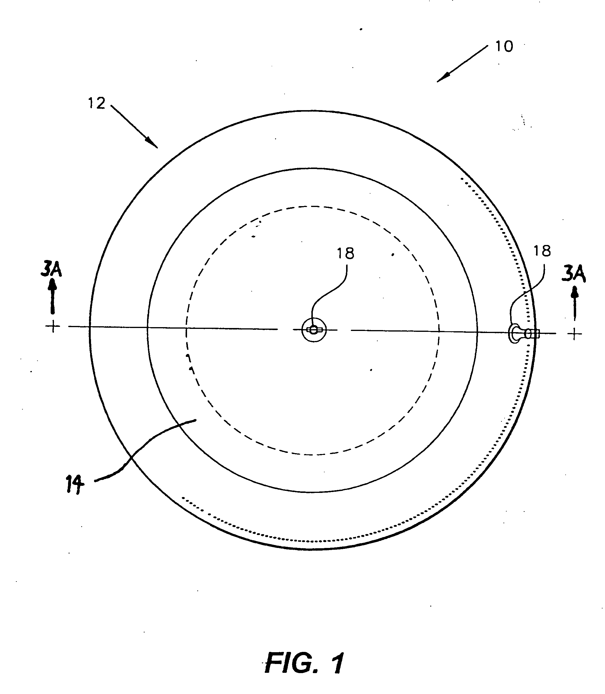
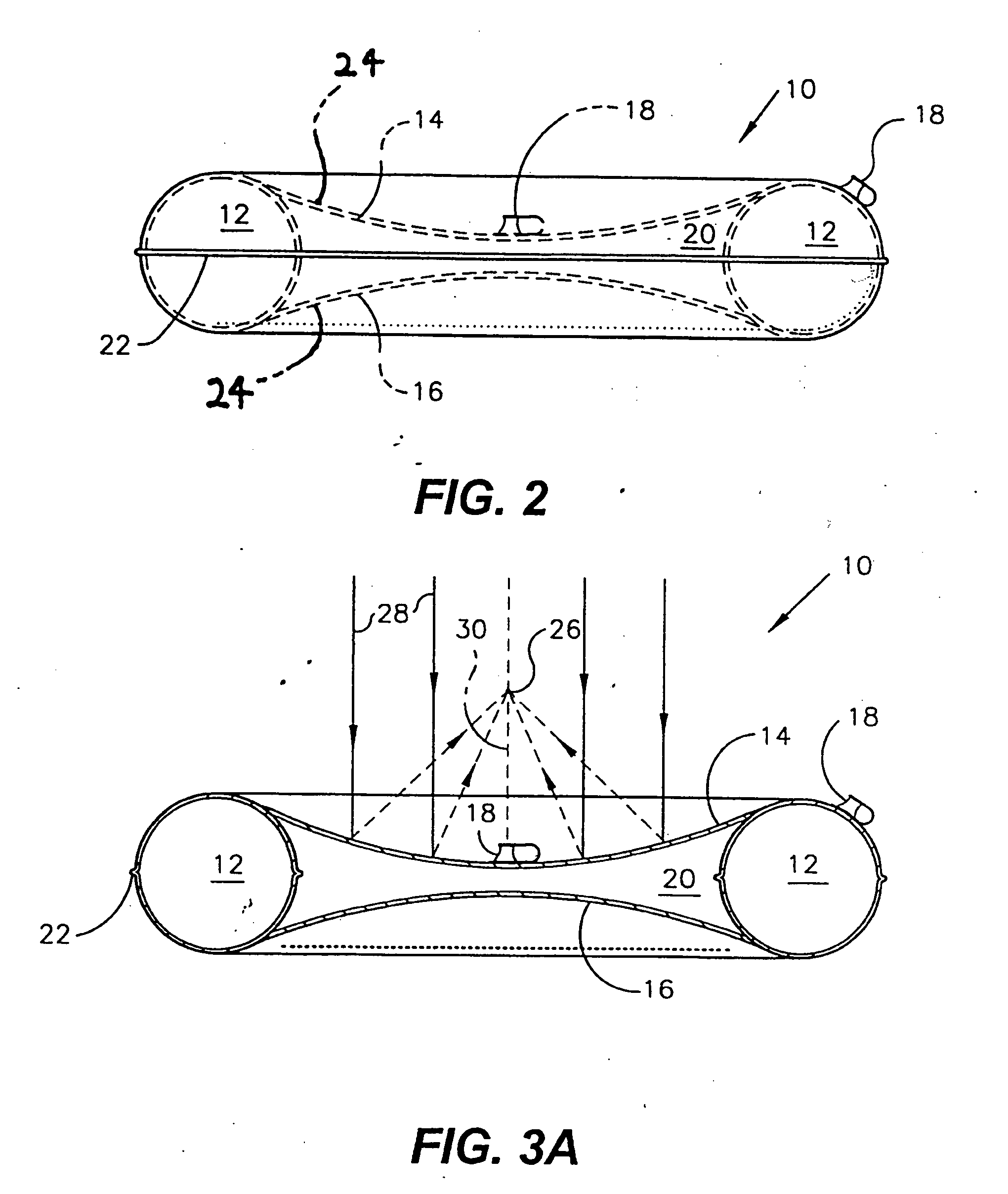
[0187] In FIGS. 1 and 2 the first main embodiment 10 having only reflective membranes is illustrated as a toroid or ring support element 12 having a circular cross-section and supporting an upper frontal elastic reflecting membrane 14 and a lower rear redundant elastic reflecting membrane 16. The figures show that the support element 12 is circular. However, it is noted that the invention can be practiced using other types of supports including those having cross-sectional shapes of a hexagon, square, rectangle, ellipse, and others. The membrane 14 has a centered inflation valve 18 (as an example of an inflation means for inflating the reflector chamber). The inflatable toroidal support structure 12 also has a gas valve 18 (as an example of an inflation means for inflating the support ring) for inflation to form a rigid ring (two valves are shown for separate inflation of the ring support and the center reflector chamber).

[0188] The reflective membranes 14 and 16 are pre-formed (dur...

first embodiment

[0192]FIG. 4 shows the first embodiment having a pressure-deformable device having two reflective outer membranes and a non-reflective center membrane 15 serving to form a redundant reflector chamber.

[0193]FIG. 5 shows the appendages which can be added to the toroid 12 to implement a stable position and to attach other elements. A pair of handles 32 are positioned diametrically on the sides of the toroid 12. An apertured tab 34 is provided on a side equidistantly between the handles 32 for hanging up when in storage or the like. A pair of hanging straps 36 are attached on either side of the apertured tab 34. A storage pouch 38 is provided for storing the deflated and folded apparatus 10. A pair of bottom pouches 40 is provided for filling with dense material to stabilize an upright apparatus 10.

[0194]FIG. 6 illustrates a flexible plug valve 42 having an integrated plug 44 on the toroid 12 as exemplary of the valve for also the reflecting membrane 14. It is noted that these valves c...


PUM


Abstract

An inflatable, multifunction, multipurpose, parabolic reflector apparatus having a plurality of manufactured parabolic mirrors made from a pressure-deformable reflective covering of an inflatable ring for focusing electromagnetic energy from radio frequency radiation (RF) through the ultraviolet radiation (UV) and solar energy for (1) heating and cooking, for (2) electrical power generation, for (3) enhancing the transmission and reception of radio signals, for (4) enhancing vision in low-light environments, and for (5) projection of optical signals or images. The device also has non-electromagnetic uses, such as the collection of water. A first main embodiment utilizes two membranes, where at least one is reflective to electromagnetic radiation. A second main embodiment utilizes a reflective membrane and a transparent membrane. Portability is enhanced by complete collapsing of the inflatable device.

Description

BACKGROUND OF THE INVENTION [0001] 1. Field of the Invention [0002] The present invention relates generally to radiant electromagnetic energy concentrating, focusing and beaming devices and manufacturing methods. More specifically, the invention, in one of its preferred embodiments, is an inflatable parabolic reflector device made from pressure-deformable reflective membranes supported by an integral inflatable ring for focusing electromagnetic energy from radio frequency radiation (RF) through the ultraviolet radiation (UV) including solar energy for (1) heating or cooking, (2) electrical power generation, (3) enhancing the transmission or reception of radio signals, (4) enhancing vision in low-light environments, and / or (5) projection of optical signals or images. [0003] A first main embodiment utilizes two or more pressure-deformable membranes, at least one of which is reflective, to form a central reflector chamber, which can be inflated to either sub-ambient (as required for mo...

Claims


Application Information

Patent Timeline
IPC IPC(8): E04H15/20E04H15/38F21L4/00F21S11/00F21S13/12F21V5/00F21V7/16F21V7/18F21V33/00F24J2/36F24J2/52F24S20/30F24S23/70F24S23/71G02B5/08G02B5/10G02B26/08G10K11/28H01L31/042H01Q1/34H01Q15/00H01Q15/16H01Q15/20
CPCE04H15/20Y02B40/18F21S11/00F21S13/12F21V7/16F21V7/18F24J2/02F24J2/125F24J2/52F24J2/5271G02B5/10G02B26/0825G10K11/28H01Q1/34H01Q15/163Y02E10/42Y02E10/47Y02E10/52E04H15/38Y02A40/926F24S25/00F24S20/80F24S23/715F24S20/30F24S50/20Y02W10/37F21S11/002Y02E10/40
Inventor ESSIG, JOHN R. JR.ESSIG, JAMES M.
Owner ESSIG JOHN R JR
Learn More