Valve body for backflow prevention valve

a valve body and backflow technology, applied in the field of valve bodies, can solve problems such as parts that may have the possibility of allowing fuel leakage, and achieve the effect of stabilizing the seal quality

Inactive Publication Date: 2005-05-19
NIFCO INC
View PDF9 Cites 10 Cited by
  • Summary
  • Abstract
  • Description
  • Claims
  • Application Information

AI Technical Summary

Benefits of technology

[0016] With such a structure, when the valve is closed, that is, in a state in which the circular fin-shaped part is pushed against the circular valve seat surface and the inflow port is closed fluid-tightly, and when the internal pressure on a side of the fuel tank rises and a pressing force from the side of the fuel tank is applied on the circular fin-shaped part, the circular fin-shaped part does not deform in a direction that a projecting direction of the circular fin-shaped part is aligned with a direction parallel to the central line of movement of the valve body, thereby stably securing the seal quality of the closed valve.

Problems solved by technology

Further, there is no part that may have a possibility of allowing leakage of fuel at other parts of the valve body.

Method used


Image

  • Valve body for backflow prevention valve
  • Valve body for backflow prevention valve
  • Valve body for backflow prevention valve

Examples


Embodiment Construction

[0041] Hereunder, embodiments of the present invention will be explained with reference to FIGS. 1 to 23.

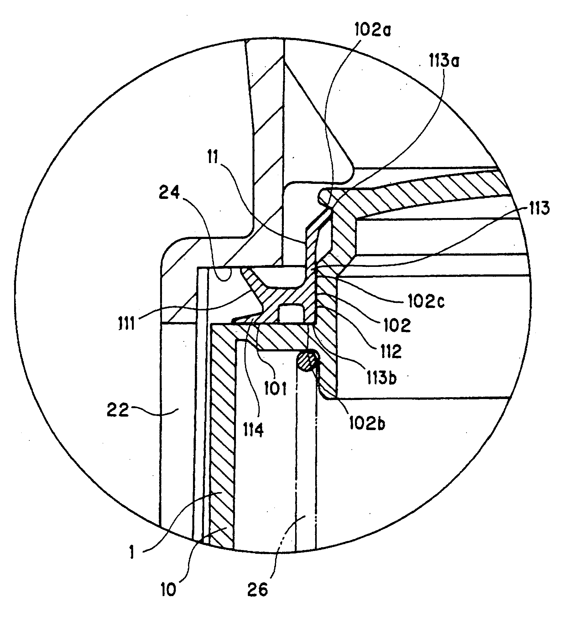
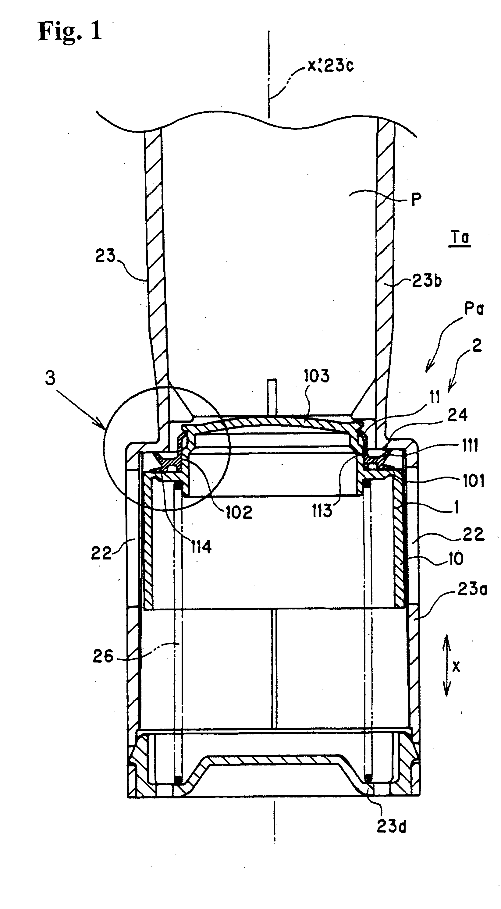
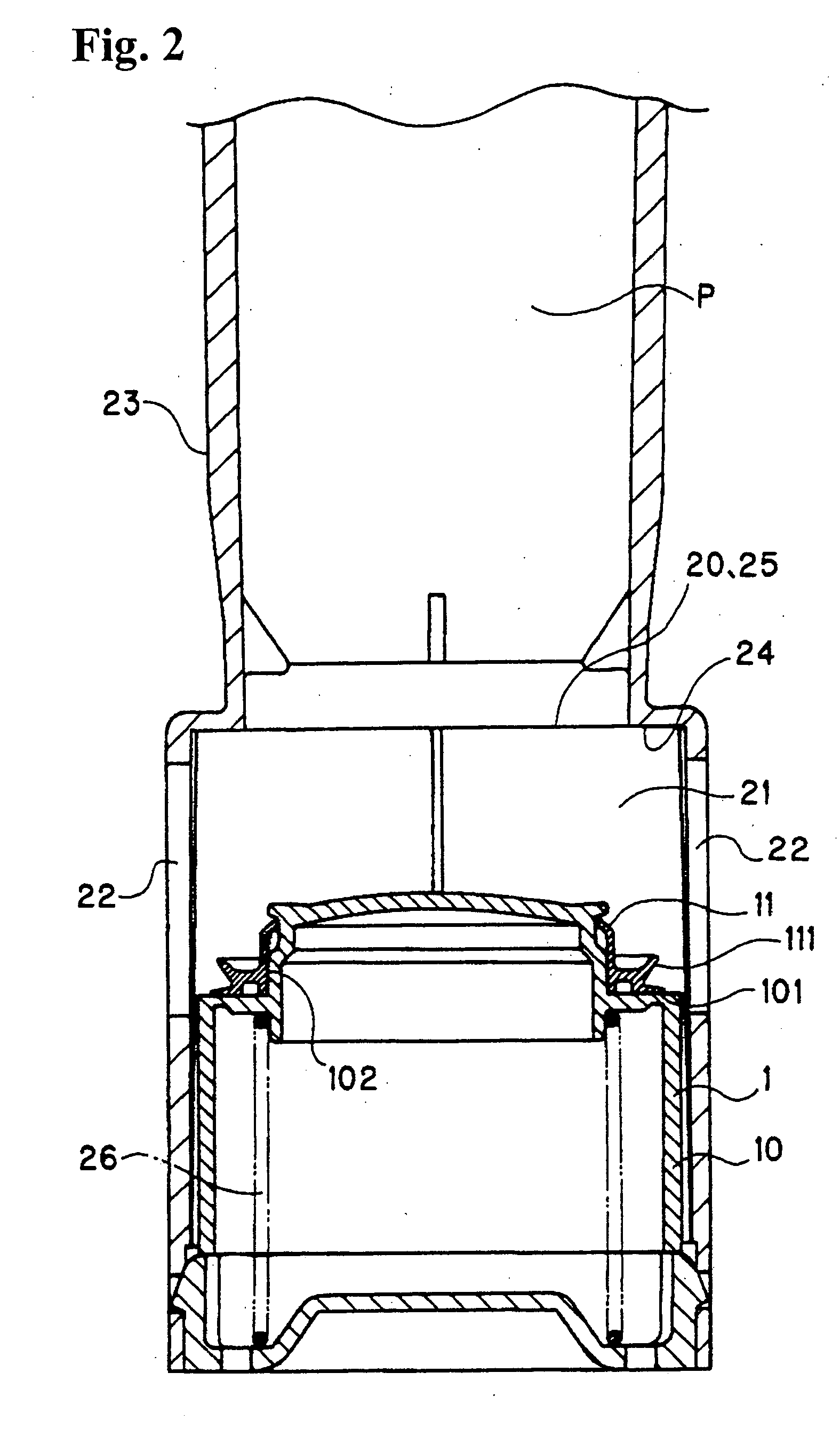
[0042] FIGS. 1 to 9 respectively show an example of a valve body 1 according to an embodiment of the present invention. FIG. 1 shows the valve body 1 in a closed valve state, FIG. 2 shows the valve body 1 in an open valve state, and FIG. 3 shows an essential part of the valve body 1 in the closed valve state. FIGS. 4 to 6 show a valve body main unit 10 constituting the valve body 1, and FIGS. 7 to 9 show an elastic seal body 11 constituting the valve body 1.

[0043] FIGS. 10 to 23 respectively show another example of the valve body 1. FIG. 10 shows the valve body 1 in the closed valve state, FIG. 11 shows the valve body 1 in the open valve state, and FIG. 12 shows an essential part of the valve body 1 in the closed valve state. FIGS. 13 to 17 show the valve body main unit 10 constituting the valve body 1, and FIGS. 18 to 23 show the elastic seal body 11 constituting the valve bod...


PUM


Abstract

A valve body main unit has a circular step surface facing a circular valve seat surface of a valve chamber formed on a terminal end part of a fuel supply path to a fuel tank and a circular groove with one groove wall extending from the circular step surface, and is normally urged in a direction of closing an inflow port surrounded by the circular valve seat surface. The valve body main unit also has an elastic seal body with a ring shape inserted into the circular groove of the valve body main unit. The elastic seal body has a circular fin-shaped part projecting from an outer perimeter part and pushed against the circular valve seat surface by the urging of the valve body main unit to close the valve.

Description

BACKGROUND OF THE INVENTION AND RELATED ART STATEMENT [0001] The invention relates to a valve body used for a backflow prevention valve. The backflow prevention valve is provided at a terminal end part of a fuel supply path for delivering fuel into a fuel tank, and functions so that during delivery of fuel from the fuel supply path, a valve is opened by a flow pressure of the delivered fuel to allow the fuel to flow into the fuel tank, and during non-delivery of fuel, the valve is closed to block the fuel inside the fuel tank from flowing back into the fuel supply path. [0002] As a backflow prevention valve for a filler pipe of a fuel tank, there is one disclosed in Patent Document 1. The prevention valve has a structure in which a seal member having a lip part seated in a valve seat part of a valve body is held between a main body member and a spring bearing member. There are several drawbacks in the prevention valve. First, the number of constituent parts is large and the assembly...

Claims


Application Information

Patent Timeline
Patent Type & Authority Applications(United States)
IPC IPC(8): B60K15/04B67D7/42B67D7/52F02M37/00F16J15/02F16K15/02F16K15/08F16K25/00
CPCB60K2015/03447B67D7/42F16K25/00F16J15/025F16K15/026B67D7/52Y10T137/7868Y10T137/7925Y10T137/7929Y10T137/86372F16K1/46B60K15/04
Inventor TAKAHASHI, HIDEAKI
Owner NIFCO INC
Why Eureka
Try Eureka