Self-contained mobile fueling station

a self-contained, fueling station technology, applied in the direction of liquid handling, electrochemical generators, packaging goods types, etc., can solve the problems of insufficient fuel capacity, difficult (expensive) transportation, testing, etc., and achieve the effect of optimizing the fill ra

Inactive Publication Date: 2005-05-19
AIR PROD & CHEM INC
View PDF12 Cites 49 Cited by
  • Summary
  • Abstract
  • Description
  • Claims
  • Application Information

AI Technical Summary

Benefits of technology

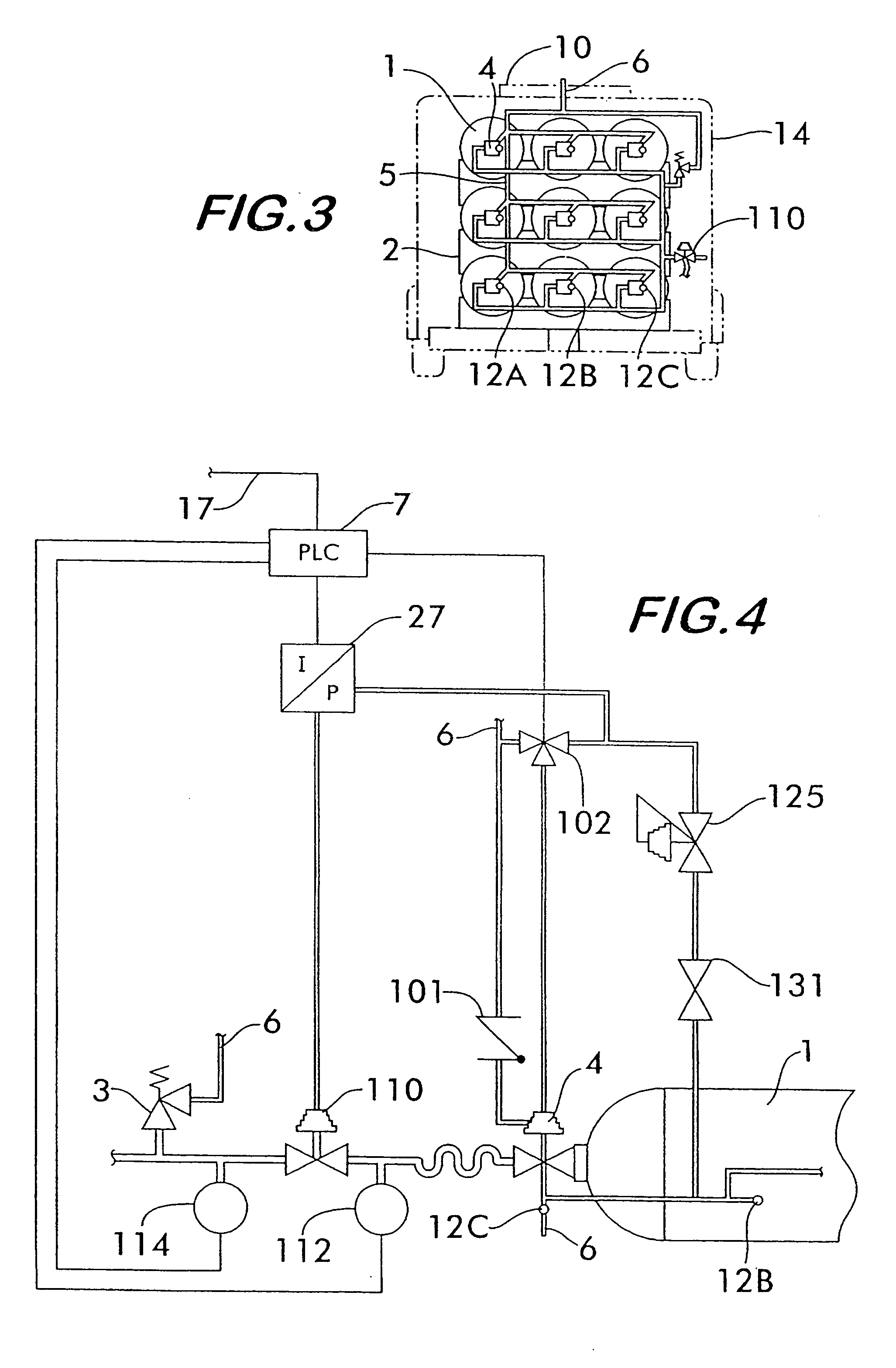
[0046] There are several variations of the method for controlling the rate of delivery of the pressurized fluid. In one variant, the step of establishing a predetermined rate of pressure rise includes multiple sub-steps. The first sub-step is to generate an electric signal convertible to a low pressure gas signal. The second sub-step is to amplify the low pressure gas signal. The third sub-step is to control a fill pressure in the receiving tank.
[0047] In another variation, the step of maintaining the predetermined rate of pressure rise includes multiple sub-steps. The first sub-step is to provide a pressure control device in communication with the conduit or another conduit through which the pressurized fluid flows at an actual pressure before entering the receiving tank, the pressure control device adapted to increase or decrease the actual pressure of the pressurized fluid. The second sub-step is to calculate periodically a rate of pressure rise over time. The third sub-step is to command the pressure control device to decease the actual pressure when the rate of pressure rise is greater than the established predetermined rate of pressure rise, and to increase the actual pressure when the rate of pressure rise is less than the established predetermined rate of pressure rise.
[0048] In another variation of the method, the rate of delivery is controlled as a function of either a percentage of a designated target pressure already achieved, or a percentage of a designated target pressure yet to be achieved during a remaining portion of the predetermined time period. In a variant of this variation, the function is linear. In another variant, the function is geometric. In yet another variant, the receiving tank has an instantaneous thermodynamic state and the function varies over time with any changes in the instantaneous thermodynamic state to provide an optimal rate of fill.
[0049] Another embodiment is a method for controlling a rate of delivery of a pressurized hydrogen gas at 5,000 psig or greater from at least on

Problems solved by technology

Since there is not an established hydrogen fueling infrastructure in place, some manufacturers are installing fixed hydrogen fueling stations at test sites and elsewhere.
Testing is taking place throughout North America without sufficient capability to fuel the test vehicles away from the fixed hydrogen fueling stations.
These events are taking place at many locations where hydrogen fueling is needed but is not available.
However, these cylinders are very heavy and difficult (expensive) to transport.
There exists a void in the availability of fuel for hydrogen-powered vehicles.
Government and industry demonstration projects are hampered by the inability to fuel the prototype vehicles being tested and demonstrated.
Although the prior art includes various types of mobile fueling stations, none of these stations satisfy the cur

Method used


Image

  • Self-contained mobile fueling station
  • Self-contained mobile fueling station
  • Self-contained mobile fueling station

Examples


Embodiment Construction

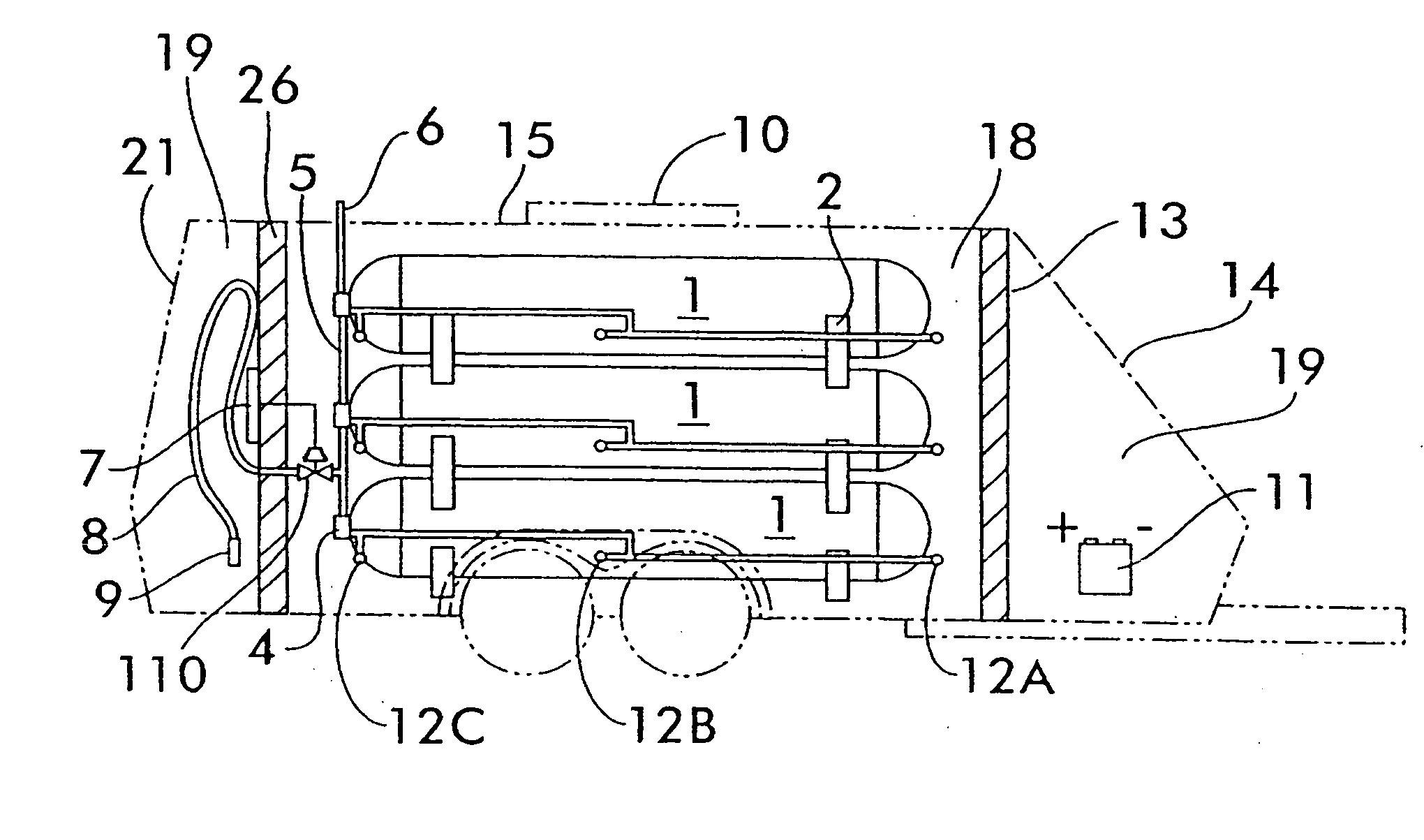
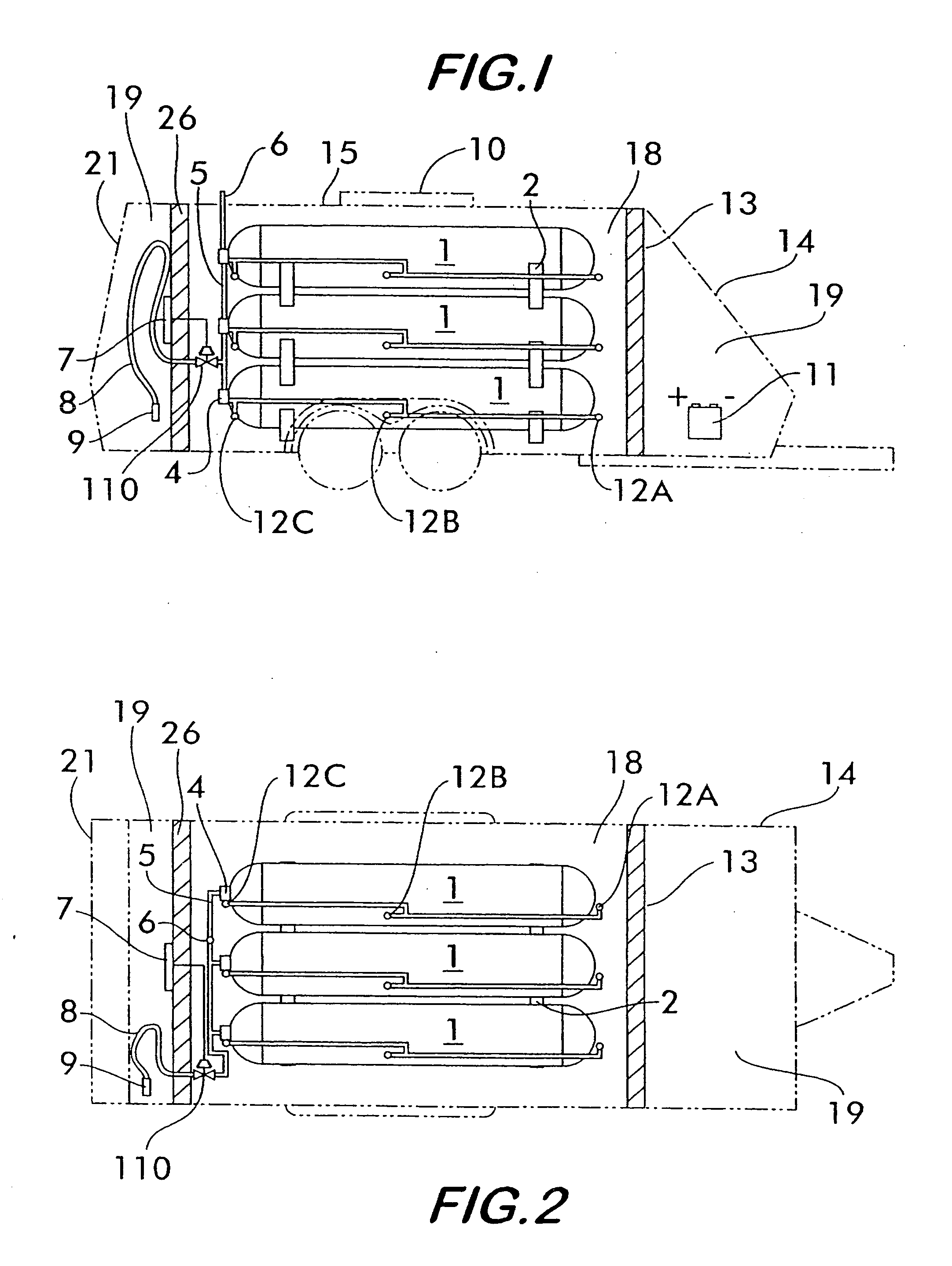
[0059] The present invention is a self-contained self-powered mobile fueling station that satisfies a growing need in building a hydrogen infrastructure. The fueling station leverages the benefits of cascade filling to optimize the use of available pressures and volume to provide an optimal rate of filling the fuel tank of a hydrogen-powered vehicle. Since the fueling station is self-powered, its delivery of fuel to the vehicle does not need any additional compression, and therefore does not require any hook-up to external electric power or other external utilities.

[0060] Automatic filling of a vehicle tank by the fueling station is provided by use of PLC control of interlocked solenoid operated valves. The valves are actuated either by a portion of the hydrogen gas inventory or by a regulated gas from a dedicated high-pressure cylinder, which is safer than manual operation of the valves. Power required to operate the PLC is provided by a deep cycle battery, which is recharged by r...


PUM

PropertyMeasurementUnit
Pressureaaaaaaaaaa
Timeaaaaaaaaaa
Pressureaaaaaaaaaa

Abstract

A mobile self-contained self-powered station having a plurality of vessels delivers a pressurized fluid to a receiving tank (e.g., a fuel tank of a hydrogen-powered vehicle) without using mechanical compression, external electric power, or other external utilities. The station includes first and second vessels, a conduit in fluid communication with the receiving tank and each of the first and second vessels, means for transferring at least a portion of a quantity of the pressurized fluid from the first vessel to the receiving tank, means for measuring continuously a pressure differential between the increasing pressure in the receiving tank and the decreasing pressure in the first vessel, means for discontinuing the transfer from the first vessel when a predetermined limit value is reached, and means for transferring at least a portion of a quantity of the pressurized fluid from the second vessel to the receiving tank.

Description

BACKGROUND OF THE INVENTION [0001] The present invention relates to a method and system for delivering a pressurized fluid, such as hydrogen or another compressed gas, to a receiving tank, such as a vehicle fuel tank, and in particular the invention relates to a self-powered mobile fueling station for delivering a fuel (e.g., hydrogen) at pressures of 5,000 psig or greater to fuel tanks of vehicles, such as hydrogen-powered vehicles. [0002] Although the invention is discussed herein with regard to delivery of pressurized hydrogen gas to fuel tanks of hydrogen-powered vehicles, persons skilled in the art will recognize that the invention has other applications. For example, it may be used to deliver other pressurized fluids which may or may not be used as fuels, and the pressurized fluids may be delivered to various types of receiving tanks other than vehicle fuel tanks. [0003] With the increasing interest in clean and efficient fuels, automobile manufacturers are designing and manuf...

Claims


Application Information

Patent Timeline
IPC IPC(8): F17C1/00
CPCB60S5/02Y02E60/321F17C5/06F17C2201/0109F17C2201/035F17C2201/054F17C2201/056F17C2203/0341F17C2203/035F17C2203/0663F17C2205/0107F17C2205/013F17C2205/0142F17C2205/0161F17C2205/0317F17C2205/0326F17C2205/0329F17C2205/0332F17C2205/0335F17C2205/0338F17C2205/037F17C2221/012F17C2223/0123F17C2223/036F17C2225/0123F17C2225/036F17C2227/043F17C2250/032F17C2250/034F17C2250/043F17C2250/0434F17C2250/0439F17C2250/0626F17C2250/0636F17C2250/0694F17C2250/072F17C2260/023F17C2260/025F17C2260/026F17C2260/042F17C2265/061F17C2265/065F17C2270/0105F17C2270/0168F17C2270/0184F17C1/00Y02E60/32
Inventor EICHELBERGER, DONALD PAULFARESE, DAVID JOHNCOHEN, JOSEPH PERRYCOLWELL, RICHARD LAYTON
Owner AIR PROD & CHEM INC
Why Eureka
Try Eureka