Method for casting a directionally solidified article

a directionally solidified and article technology, applied in the direction of manufacturing tools, foundry patterns, moulding apparatus, etc., can solve the problems of ds and sx, stray grain formation, ds and sx, etc., to improve the thermal gradient, improve the heat extraction efficiency, and improve the effect of heat extraction efficiency

Active Publication Date: 2005-05-19
ANSALDO ENERGIA SWITZERLAND AG
View PDF7 Cites 15 Cited by
  • Summary
  • Abstract
  • Description
  • Claims
  • Application Information

AI Technical Summary

Benefits of technology

[0008] One aspect of the present invention includes a method for manufacturing one or more directionally solidified (DS) or single crystal (SX) articles which avoids a direction of the heat flux which deviates substantially from the vertical withdrawal direction at protruding geometrical features of the cast part while increasing the thermal gradient in the vertical withdrawal direction within the cast part.
[0009] When a protruding geometrical feature, which means a steep increase in outer surface area, like a shroud passes the impingement area of the gas jets, the inert gas flow is reduced or even stopped to prevent excessive cooling and to prevent a heat flux direction in the cast part which deviates from the vertical withdrawal direction. Such a deviating heat flux direction causes an inclined solidification front, which in turn can cause undesired inclined DS grain boundaries or stray grain formation in both, DS and SX. When such a protruding geometrical feature has passed the impingement area of the gas jets, the inert gas flow is restored to a value adjusted to the geometry of the cast part presently passing the impingement area.
[0010] Advantageously the patches of heat extraction generated by gas nozzles are positioned at a constant height below the baffle and around the circ

Problems solved by technology

Such a deviating heat flux direction causes an inclined solidification front, which in turn

Method used


Image

  • Method for casting a directionally solidified article
  • Method for casting a directionally solidified article
  • Method for casting a directionally solidified article

Examples


Embodiment Construction

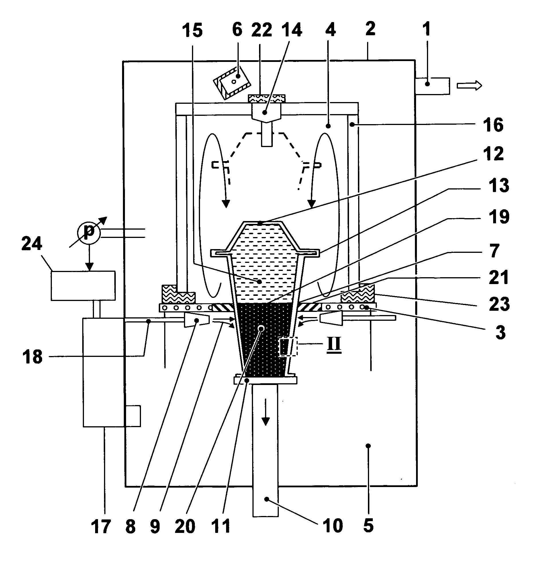
[0017] The invention of casting directionally solidified (DS) or single crystal (SX) articles such as blades or vanes or other parts of gas turbine engines is described in greater detail below with reference to an exemplary embodiment. In this case, FIG. 1 shows in diagrammatic representation an exemplary embodiment of an apparatus for carrying out the process according to the present invention. The apparatus shown in FIG. 1 has a vacuum chamber 2 which can be evacuated by means of a vacuum system 1. The vacuum chamber 2 accommodates two chambers 4, 5 which are separated from one another by a baffle (radiation and gas flow shield) 3, which may be extended with flexible fingers or brushes 21, and are arranged one above the other, and a pivotable melting crucible 6 for receiving an alloy, for example a nickel base superalloy. The upper one 4 of the two chambers is designed so that it can be heated. The lower chamber 5, which is connected to the heating chamber 4 through an opening 7 i...


PUM

PropertyMeasurementUnit
Lengthaaaaaaaaaa
Thicknessaaaaaaaaaa
Pressureaaaaaaaaaa

Abstract

A method of casting a directionally solidified (DS) or single crystal (SX) article with a casting furnace having a heating chamber (4), a cooling chamber (5), a separating baffle (3) between the both chambers includes a first step in which the shell mould (12) is filled with liquid metal (15), and the liquid metal (15) is directionally solidified by withdrawing the shell mould (12) from the heating to the cooling chamber (4, 5). An inert gas impinges from nozzles (8) arranged below the baffle (3) on the shell mould (12) and in steep transitions in outer surface area of the shell mould (12) the flow of the inert gas (9) is reduced or even stopped and when a protruding geometrical feature has passed the impingement area of the gas jets, the gas flow (9) is restored to a value adjusted to the geometry of the cast part presently passing the impingement area.

Description

[0001] This application claims priority to European application number 03104109.8, filed 6 Nov. 2003, the entirety of which is incorporated by reference herein.FIELD OF INVENTION [0002] The invention relates to a method for casting a directionally solidified (DS) or single crystal (SX) article. BACKGROUND OF THE INVENTION [0003] The invention proceeds from a process for producing a directionally solidified casting and from an apparatus for carrying out the process as is described, for example, in U.S. Pat. No. 3,532,155. The process described serves to produce the guide vanes and rotor blades of gas turbines and makes use of a furnace which can be evacuated. This furnace has two chambers which are separated from one another by a water-cooled wall and are arranged one above the other, the upper chamber of which is designed so that it can be heated and has a pivotable melting crucible for receiving material to be cast, for example a nickel base alloy. The lower chamber, which is conne...

Claims


Application Information

Patent Timeline
IPC IPC(8): B22D27/04
CPCB22D27/045
Inventor BALLIEL, MARTINECKARDT, DIETRICHKONTER, MAXIMWEILAND, ANDREAS
Owner ANSALDO ENERGIA SWITZERLAND AG
Why Eureka
Try Eureka