Sealing device, and rolling bearing and hub unit incorporating the sealing unit

a sealing device and hub unit technology, applied in mechanical equipment, rotary machine parts, transportation and packaging, etc., can solve the problems of reducing sealing performance at the respective slidably contacting regions, difficult to secure sealing performance, and difficult to secure sufficient sealing performance, so as to improve sealing performance and reduce the strain generated in the axially oriented sealing lip. , the effect of improving sealing performan

Inactive Publication Date: 2005-05-19
NSK LTD
View PDF9 Cites 15 Cited by
  • Summary
  • Abstract
  • Description
  • Claims
  • Application Information

AI Technical Summary

Benefits of technology

[0026] In accordance with the seal assembly according to the present invention as described above and the rolling bearing and hub unit implemented therewith, the sealing performance can be improved.
[0035] Furthermore, in the case of the seal assembly according to the sixth aspect, it is possible to prevent foreign matters from entering the slidably contacting region between the radially inner edge of the tip end portion in the axially oriented seal lip and the side surface of the mating member. Because of this, the abrasion of this slidably contacting region can be inhibited by preventing foreign matters from being bitten by this slidably-contacting region. Accordingly, in the case of this structure, the sealing performance can be improved. In addition to this, since the above auxiliary seal lip is formed in order to project from the tip edge of the above axially oriented seal lip, the cost does not substantially rise. Meanwhile, the above auxiliary seal lip sufficiently works as long as it prevents the entrance of foreign matters, and therefore the pressing force of this auxiliary seal lip need not be increased. Because of this, it is possible to make small or null the abrasion at the slidably contacting region between the tip edge of this auxiliary seal lip and the above side surface of the mating member. Also, even if there is some abrasion at this slidably contacting region, no influence thereof is exerted upon the sealing performance of the slidably contacting region between the side surface of the mating member and the radially inner end of the tip edge of the above axially oriented seal lip. Furthermore, since the pressing force of the above auxiliary seal lip can be significantly decreased, it is possible to prevent the pressing force of the above outer seal lip from excessively decreasing because of the provision of this auxiliary seal lip 19.

Problems solved by technology

In this manner, also in the case where the pressing force is excessively decreased, the sealing performance is degraded at the respective slidably contacting regions.
However, in this case, it becomes difficult to secure the sealing performance when the above slinger 6 moves apart from the above sealing member 7.
However, in this case, the abrasion of the tip edge of the outer seal lips 14 and 14a is even more likely to make it difficult to secure a sufficient sealing performance.
However, the provision of such another seal lip may increase the torque of the rolling bearing and substantially raise the cost of the seal assembly for the rolling bearing.

Method used


Image

  • Sealing device, and rolling bearing and hub unit incorporating the sealing unit
  • Sealing device, and rolling bearing and hub unit incorporating the sealing unit
  • Sealing device, and rolling bearing and hub unit incorporating the sealing unit

Examples


Embodiment Construction

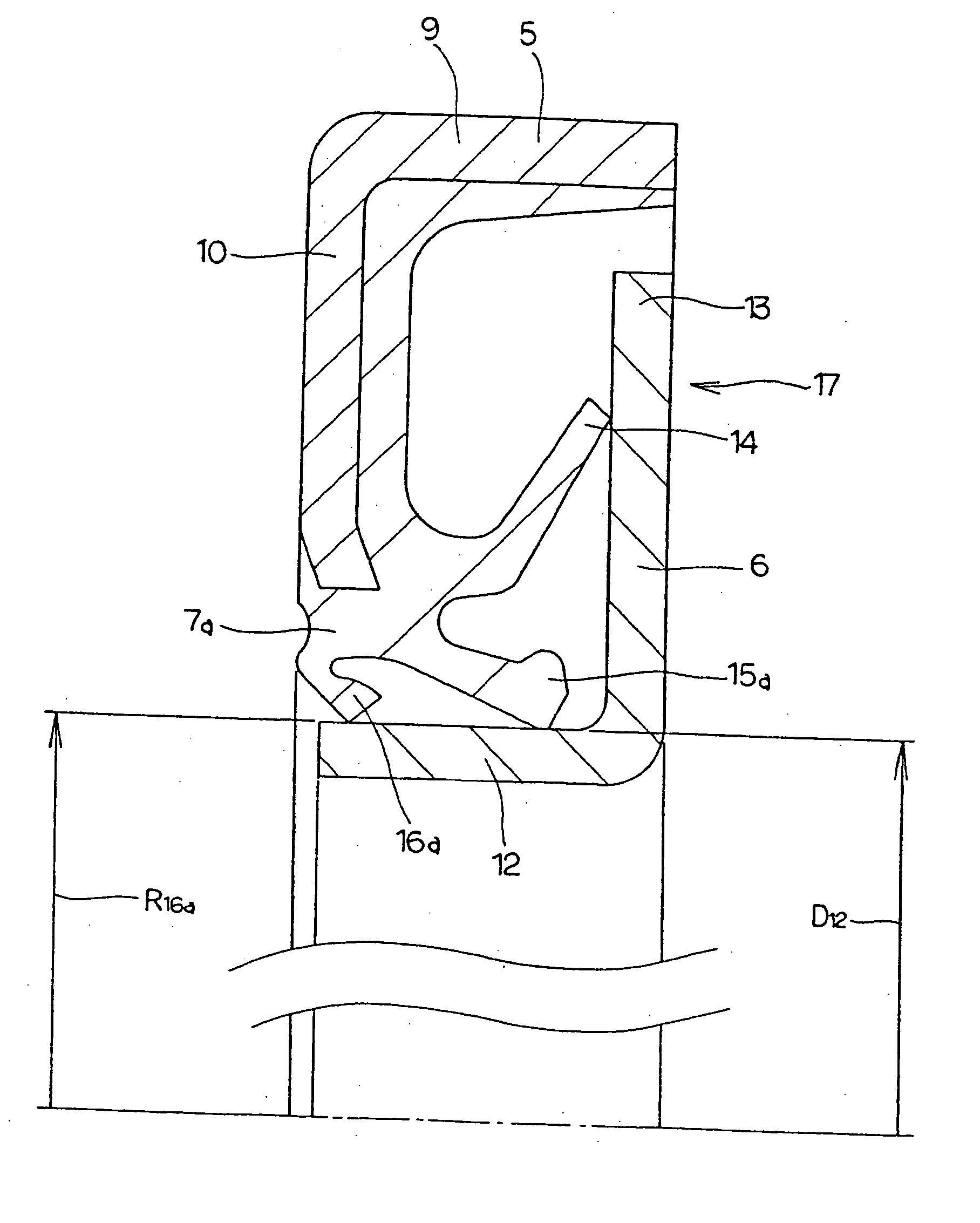
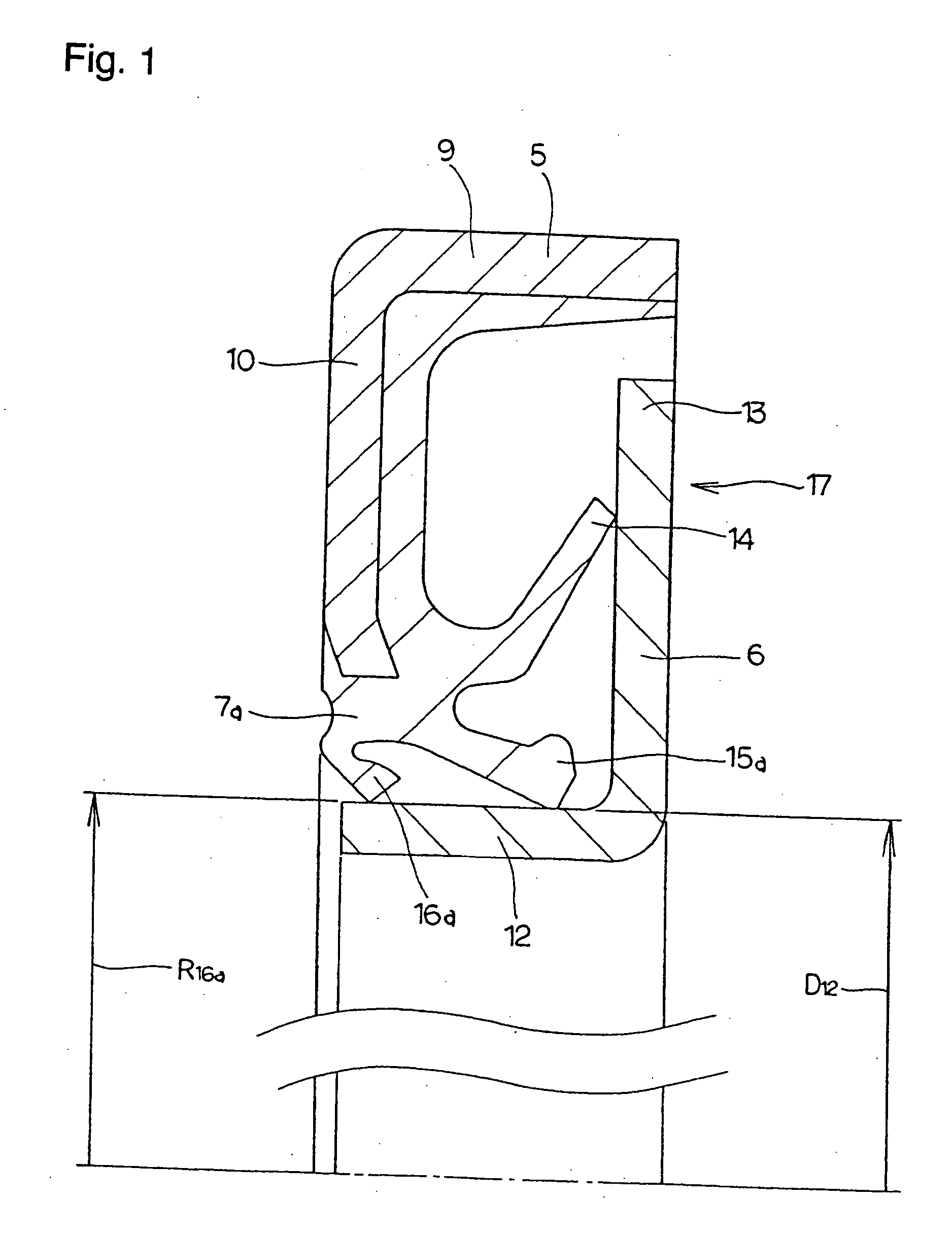
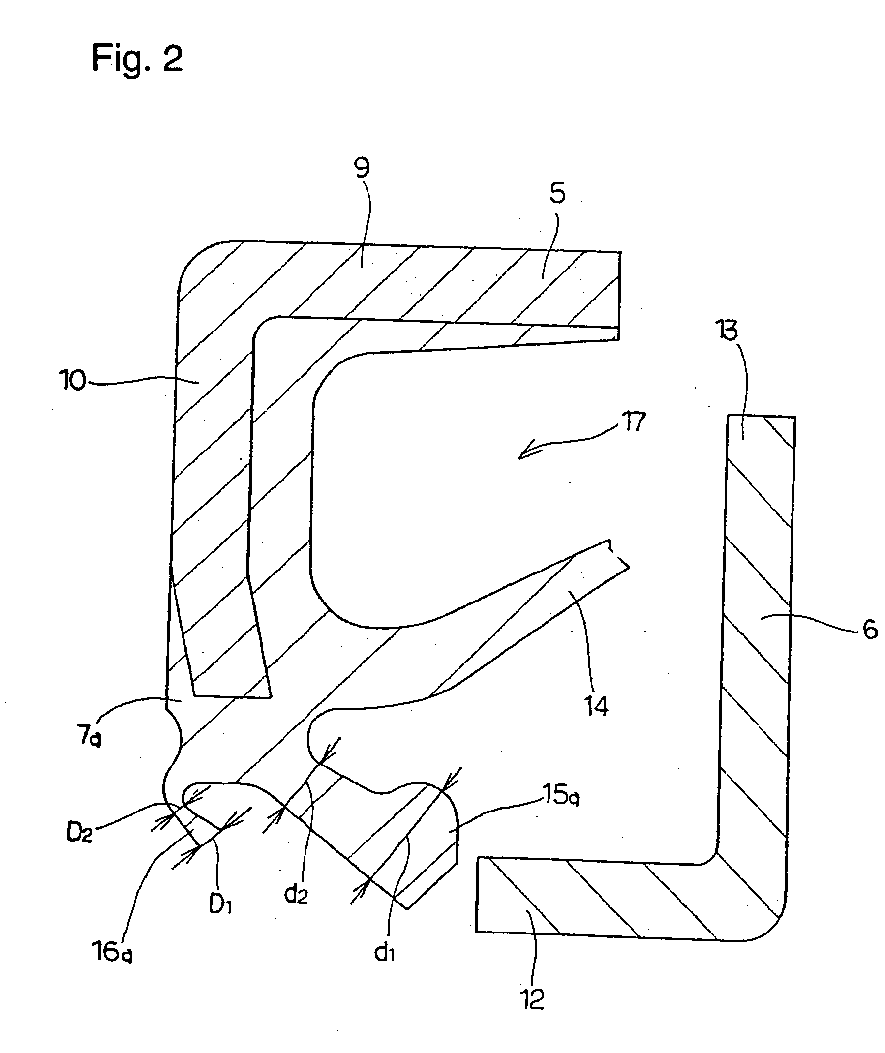
[0063]FIGS. 1 and 2 show a first example of the embodiment of the present invention corresponding to the first to seventh aspects. The seal assembly 17 according to the present invention is composed of a metal core 5, a slinger 6 and a sealing member 7a. The metal core 5 among these elements is formed in a single body by punching process, such as press work, and plastic-working process of a metallic plate such as a low-carbon steel plate. The metal core 5 is formed in a generally annular ring shape having an L-shaped cross section, and composed of a radially outer cylindrical portion 9 which can be internally fitted and fixed to the inner peripheral surface of the end portion of the outer race 8 (see FIG. 25) of the rolling bearing and an inner circular ring portion 10 which is bent inwardly in the radial direction from the end edge at the axially inner end of this radially outer cylindrical portion 9 (the left edge as illustrated in FIGS. 1 and 2).

[0064] The above slinger 6 is als...


PUM


Abstract

A seal member with its base end connected to a metal core has three seal lips. The thickness of the tip end of the intermediate seal lip in the intermediate position is d1, and the thickness of the base end is d2. The thickness of the tip end of the innermost inner seal lip is D1 and that thickness of the base end is D2. In this case, at least part of the base end of the intermediate seal lip and inner seal lip has its thickness regulated to be 0.2·d1≦d2≦0.8·d1, and 0.5·D1≦D2<D1. The tip edge of the inner seal lip is fitted onto the outer peripheral surface of the radially inside cylindrical portion of a slinger with substantially zero interference. Consequently, even if the slinger and metal core are displaced relative to each other, excellent seal performance is secured while increase of torque is inhibited.

Description

TECHNICAL FIELD [0001] The seal assembly, the rolling bearing and the hub unit in accordance with the present invention are related, for example, to an improvement of the seal assembly for rolling bearing to be incorporated into the rotatable supporting structure of the support device etc. for the wheels of an automobile or the like. BACKGROUND OF THE INVENTION [0002] The rotatable supporting structures of various types of mechanical devices are assembled with a rolling bearing such as a ball bearing, a cylindrical roller bearing, a tapered roller bearing or the like. This kind of a rolling bearing is provided with a seal assembly for the purpose of preventing the grease applied inside of this rolling bearing from leaking out of the rolling bearing, and also preventing various types of foreign objects such as rain water, mud, dust and the like from entering the inside of the rolling bearing. FIGS. 25 to 27 show three exemplary structures of the seal assembly provided at the opening ...

Claims


Application Information

Patent Timeline
Patent Type & Authority Applications(United States)
IPC IPC(8): B60B27/00F16C33/78F16J15/32
CPCB60B27/00B60B27/0005B60B27/0073F16C19/186F16C33/7883F16C2326/02F16J15/3264B60B27/0094F16C2240/40
Inventor MATSUI, MASAHITOYUKAWA, KINJI
Owner NSK LTD
Why Eureka
Try Eureka