
Brush tufting machine

Inactive Publication Date: 2005-05-19
FIRMA G B BOURCHERIE NV
View PDF3 Cites 0 Cited by
  • Summary
  • Abstract
  • Description
  • Claims
  • Application Information

AI Technical Summary

Benefits of technology

[0004] The invention allows, for one thing, to double the production capacity of a brush tufting machine at moderate additional expense and, for another, to ensure continued operation of the machine at half the production capacity in the event of a malfunction.
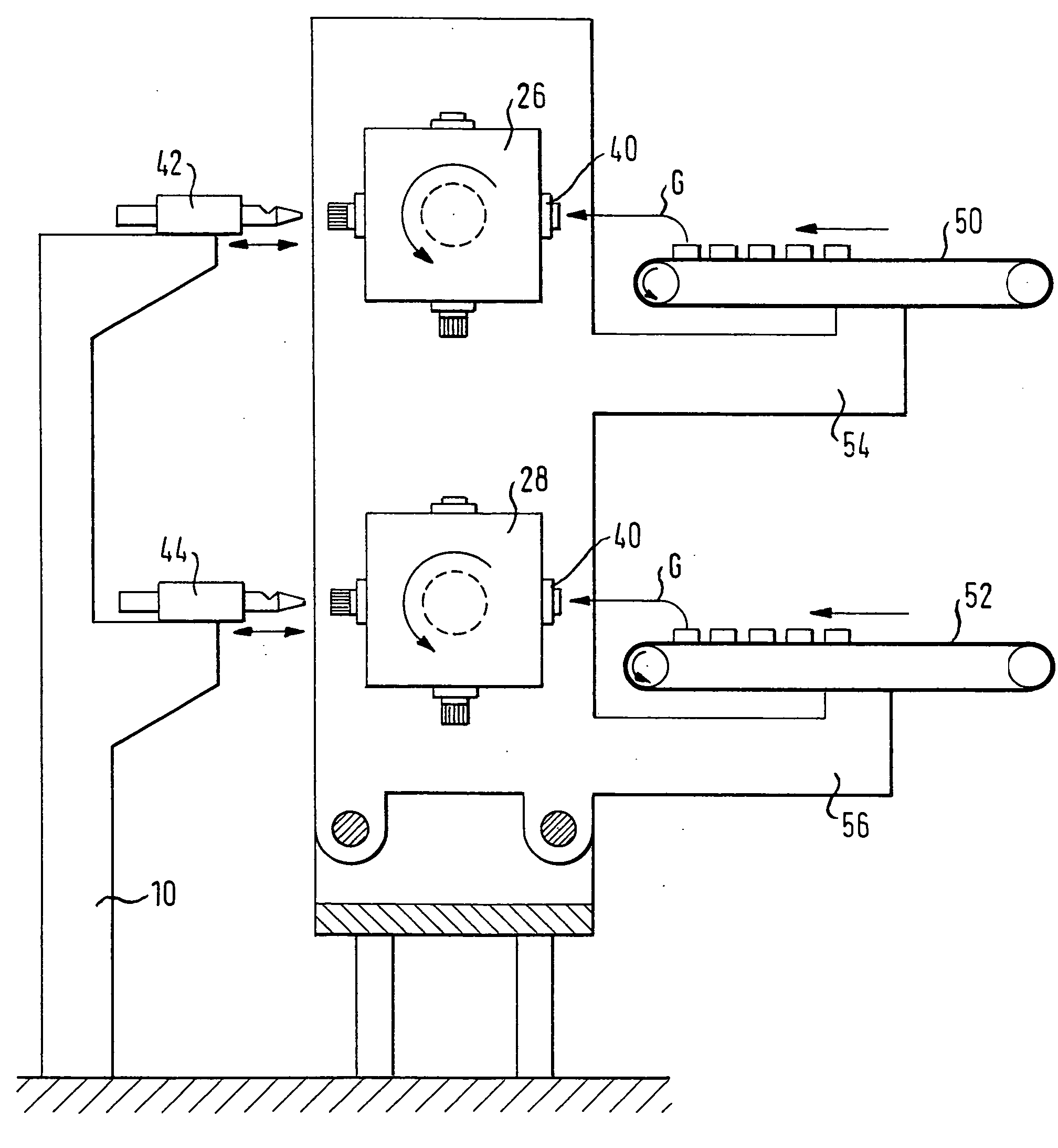
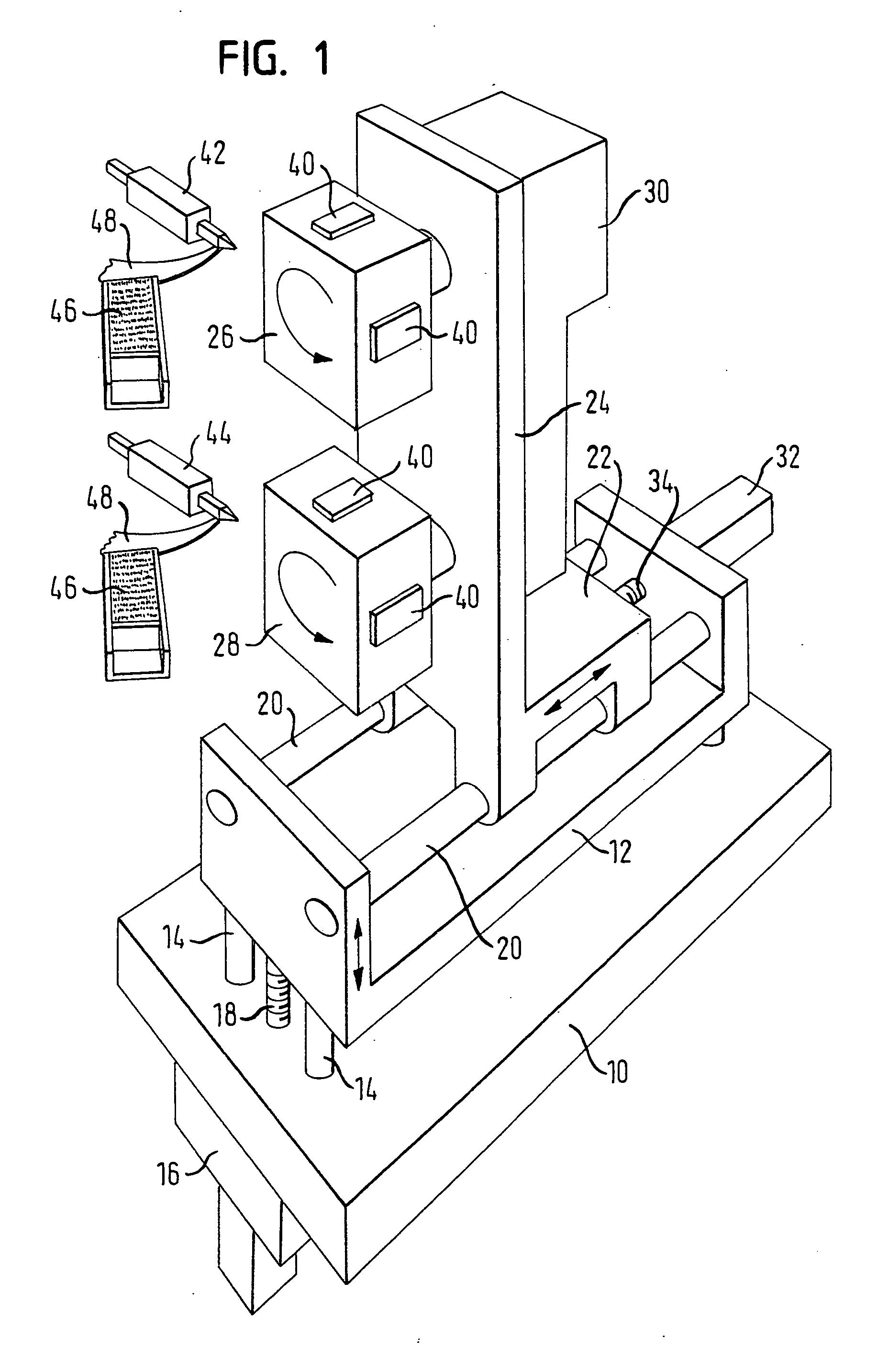
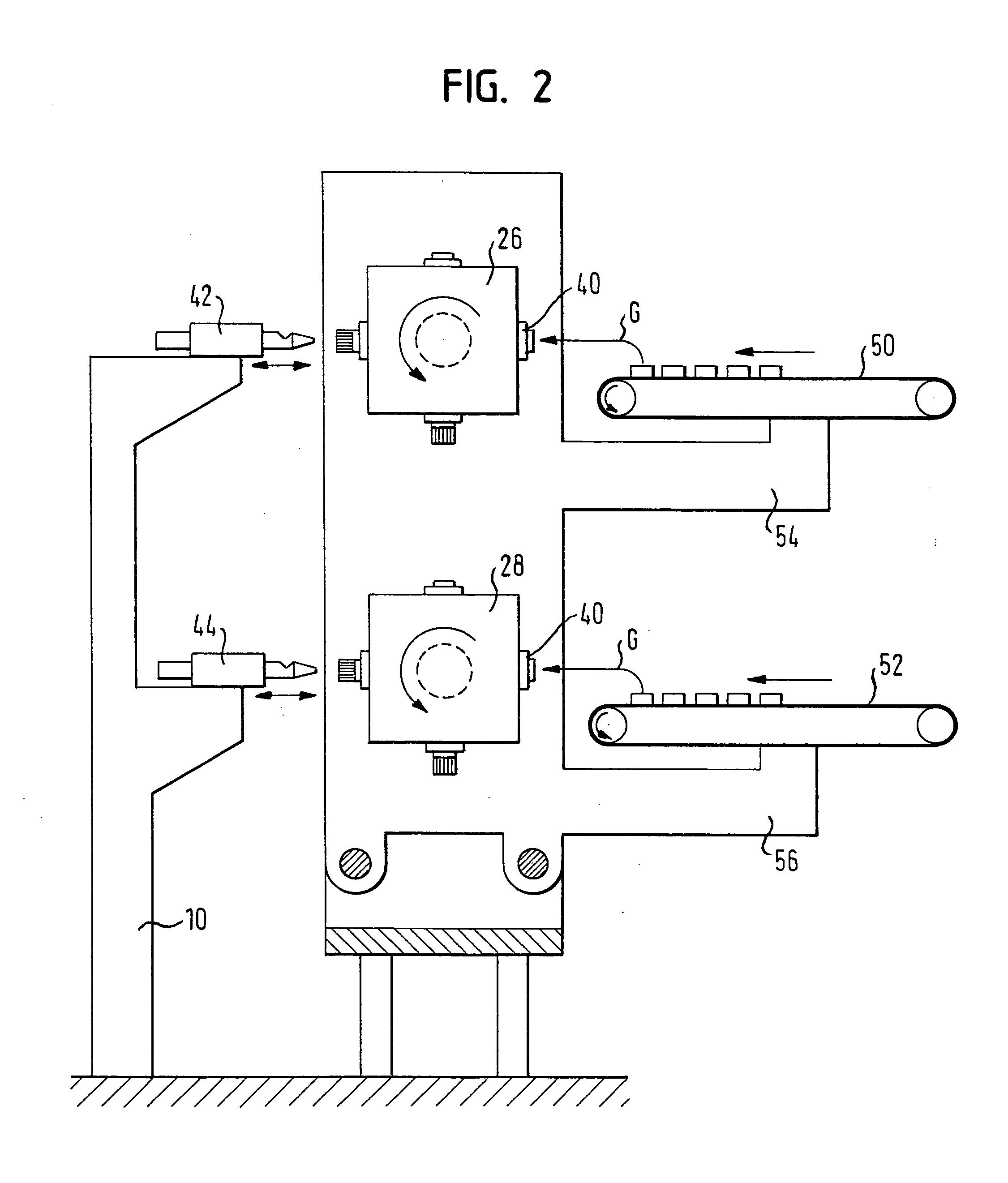
[0005] In the brush tufting machine according to the present invention, two drums are arranged at the slide at a distance from each other and mounted for rotation about two parallel axes. Associated with each drum is a tufting tool. Both drums are reciprocated by the slide simultaneously in at least two mutually orthogonal directions. The invention is based on the idea that, in the great majority of cases, failure of a brush tufting machine is caused by malfunctions appearing in the area of the tufting tool and the brush body supply, whereas malfunctions involving the slide drive occur quite rarely. Accordingly, when there is a malfunction in the area of a tufting tool or the brush body feed, the machine can continue to work at half the production capacity, putting to use the other tufting tool and the associated brush body feeder. With both tufting tools in operation, production capacity may be doubled, as compared to a conventional brush tufting machine. Accommodation of a second drum and a second stuffing tool in the machine requires only slight modifications to be made on the machine tool table and on the slide. It is therefore possible to double the production capacity involving little additional expenditure.

Problems solved by technology

In the event of a malfunction of such a brush tufting machine, the machine needs to be stopped, resulting in a complete loss of production.

Method used


Image

  • Brush tufting machine
  • Brush tufting machine
  • Brush tufting machine

Examples


Embodiment Construction

[0011] In the brush tufting machine shown in FIG. 1, a machine tool table 10 is provided, on which a lifting frame 12 is guided on slide bars 14 for vertical reciprocating movement. A drive 16 that is arranged beneath the machine tool table 10 and is coupled to the lifting frame 12 by a spindle 18 drives the lifting frame, as indicated by a vertical double arrow. The lifting frame 12 carries two horizontal slide bars 20 on which a slide 22 is guided for reciprocating movement. The slide 22 is rigidly connected to a vertical supporting plate 24 having two drums 26, 28 mounted thereon for rotation on one horizontal shaft each, the drums 26, 28 being arranged vertically one on top of the other and at a distance from each other. The drums 26, 28 are indexable in steps of 90°. They are driven synchronously by a shared indexing drive 30. As an alternative, each drum 26, 28 may have a drive of its own. The slide 22 is driven to perform a horizontal reciprocating movement by a drive 32 arra...


PUM


Abstract

A brush tufting machine includes a machine tool table having a slide that is displaceably guided on the machine tool table in at least two mutually orthogonal directions. A first drive is provided for reciprocating the slide in a first one of the two directions, and a second drive is provided for reciprocating the slide in a second one of the two directions. Two drums are mounted at the slide for rotation about parallel, spaced axes. Two tufting tools are arranged at the machine tool table at a distance from each other and each in opposition to a peripheral surface of one of the drums. The peripheral surface of each drum has brush body holders arranged thereon.

Description

FIELD OF THE INVENTION [0001] The present invention relates to a brush tufting machine, in particular for making toothbrushes. BACKGROUND OF THE INVENTION [0002] Conventional brush tufting machines have a machine tool table having a slide that is displaceably guided thereon in two mutually orthogonal directions. A drum is rotatably mounted at the slide. A plurality of brush body holders is arranged on the peripheral surface of the drum. A tufting tool is arranged at the machine tool table in opposition to the peripheral surface of the drum. A brush body feeder transports individual brush bodies to the drum to deliver the brush bodies to a brush body holder one at a time. This can be performed manually or mechanically, e.g. by means of a gripper or a robot. The slide, and the drum along with it, are reciprocated in the two directions by a pair of drives, while the tufting tool is reciprocated perpendicularly to the peripheral surface of the drum. [0003] In the event of a malfunction ...

Claims


Application Information

Patent Timeline
IPC IPC(8): A46D3/04
CPCA46D3/04
Inventor BOUCHERIE, BART GERARD
Owner FIRMA G B BOURCHERIE NV
Learn More