Elastic track shoe

a technology of elastic body and track shoe, which is applied in the direction of wheel attachment, transportation and packaging, drilling equipment, etc., can solve the problems of deflection and distortion, deflection and distortion, loosening and coming off bolts, etc., and achieves the effect of preventing the peeling of the elastic body, ensuring the friction coefficient with respect to the road surface, and improving the durability of the join

Inactive Publication Date: 2005-05-19
KOMATSU LTD
View PDF16 Cites 11 Cited by
  • Summary
  • Abstract
  • Description
  • Claims
  • Application Information

AI Technical Summary

Benefits of technology

[0008] According to the invention, since the core bar is integrally formed by casting, forging or precutting, the rigidity of the track shoe can be remarkably improved compared to track shoes made from plate metal and loosening and coming-off of the bolts can be prevented without fail. In addition, since the portion of the core bar, which is defined by projection of the ground engaging face of the elastic body, is divided into two parts, the thickness of the elastic body subjected to a load can be increased irrespective of the grousers and the volume of the whole elastic body can be increased. As a result, the cutting resistance of the elastic body and the durability of the track shoe as a whole can be improved.
[0025] Preferably, the elastic body is comprised of a plurality of layers having different hardnesses and a layer closer to the core bar is harder. This prevents occurrence of strain concentration on the joint between the core bar and the elastic body so that the durability of the joint can be improved. In addition, since a portion of the elastic body in the vicinity of the tread is soft, a friction coefficient with respect to the road surface can be ensured.

Problems solved by technology

The track shoes disclosed in Japanese Utility Model Nos. 2595443 and 2606785 have the problem that since they are designed to have fastening members such as bolts welded to the core bar made from sheet metal, sufficient rigidity cannot be ensured, so that loosening and coming-off of the bolts are likely to occur resulting from occurrence of deflection and distortion.
On the other hand, the track shoe disclosed in Japanese Patent Kokai Publication No. 10-16835, which is joined to the shoe plate through the mounting brackets, can attain improved mounting strength, but has revealed such a disadvantage that the thickness of the elastic body subjected to a load cannot be increased.
This leads to strain concentration upon the elastic body, resulting in poor durability.

Method used


Image

  • Elastic track shoe
  • Elastic track shoe
  • Elastic track shoe

Examples


first embodiment

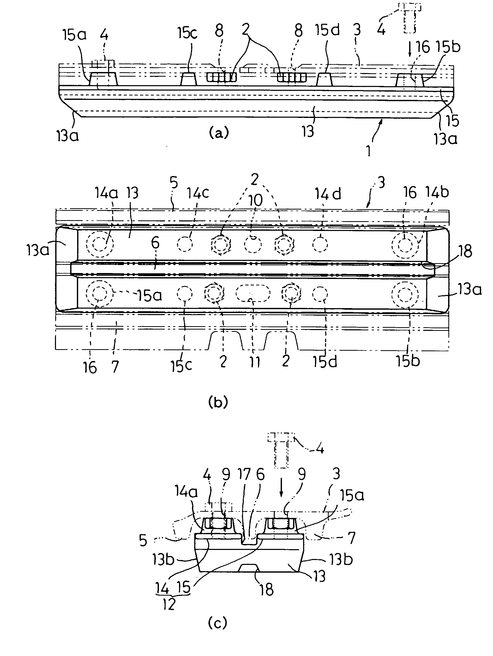
[0037] FIGS. 1(a), 1(b) and 1(c) are a front view, bottom view and side view, respectively, of an elastic track shoe constructed according to the invention.

[0038] An elastic track shoe 1 according to the first embodiment is attached to the ground engaging side of an iron shoe plate 3 by means of a plurality of bolts 4 (four bolts in the first embodiment), the shoe plate 3 being mounted to a crawler track link (not shown) with a plurality of bolts 2 (four bolts in the first embodiment) and nuts (not shown).

[0039] The shoe plate 3 has three grousers 5, 6, 7 in total, which are located at the widthwise center and widthwise ends of the shoe plate 3, extending in a longitudinal direction of its tread. The shoe plate 3 has, at its longitudinal center, bolt insertion holes 8 through which the bolts 2 pass in order to attach the shoe plate 3 to a crawler track link. Provided at positions close to both longitudinal ends are bolt insertion holes 9 through which the bolts 4 pass in order to a...

second embodiment

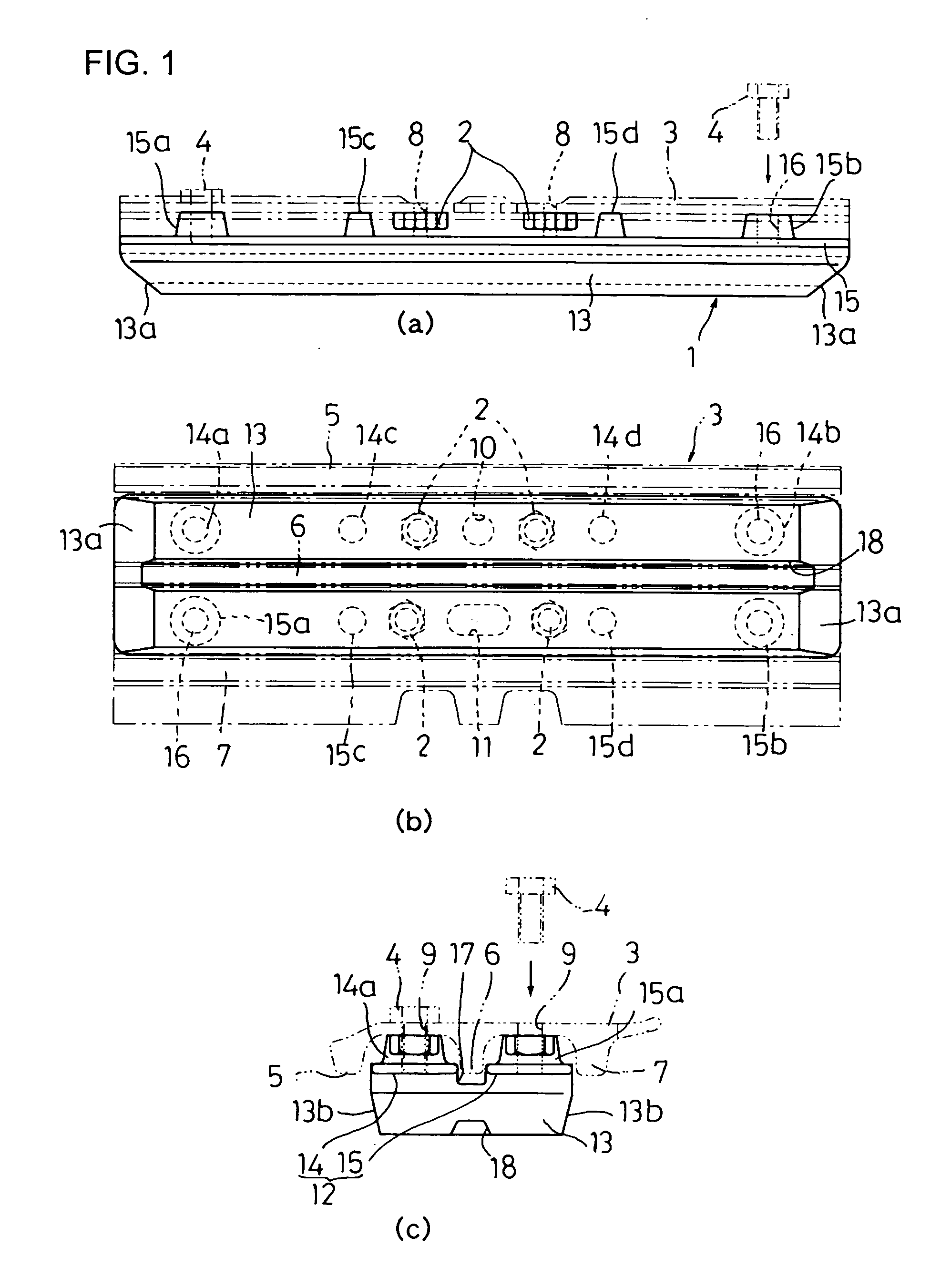
[0044]FIG. 2 is a partial sectional view of a core bar of an elastic track shoe constructed according to the invention.

[0045] The elastic track shoe of the second embodiment is the same as that of the first embodiment except the shape of the core bar. In the second embodiment, a support (boss) 21 is disposed at both longitudinal ends of each core bar portion 20 so as to somewhat project toward the ground engaging side of the core bar portion 20, and the ground engaging side of the area intermediate between the bosses 21 located at both ends is made in the form of a planar surface. The structure of this embodiment is useful particularly for the case where sufficient screw depth is required for the bolts 4 (See FIG. 1) used for attaching the core bar to the shoe plate.

[0046] In the second embodiment, each core bar portion 20 bends to the non ground engaging side at the longitudinal ends thereof, thereby forming inclined faces 22. The provision of the inclined faces 22 offers such an ...

third embodiment

[0047]FIG. 3(a) is a partial front view of a core bar of an elastic track shoe constructed according to the invention, FIG. 3(b) is a sectional view taken along line A-A of FIG. 3(a), and FIG. 3(c) is a sectional view taken along line B-B of FIG. 3(a).

[0048] The elastic track shoe of the third embodiment is similar to that of the first embodiment except the shape of the cross bar. In the third embodiment, a support 25 is formed at an end of each core bar portion 24 and another support 26 is formed at the middle part of the core bar portion 24. Provided between the supports 25 and 26 and between the support 25 and the leading end of the inclined face 27 are ribs 28. The provision of the ribs 28 allows the load received from the ground surface to be transmitted to the shoe plate without fail and also contributes to a reduction in the weight of the core bar.


PUM


Abstract

An elastic track shoe is provided wherein loosening of bolts is prevented by use of a rigid core bar and the thickness of an elastic body subjected to a load can be increased irrespective of grousers. To this end, the core bar is integrally formed by casting, forging or precutting, a ground engaging side of the core bar is covered with the elastic body, and a portion of the core bar defined by projection of a ground engaging face of the elastic body is divided into two parts.

Description

TECHNICAL FIELD [0001] The present invention relates to an elastic track shoe mounted on the ground engaging side of an iron shoe plate incorporated in a crawler track of a track-type vehicle. BACKGROUND ART [0002] Typical crawler tracks for track-type vehicles such as bulldozers and hydraulic shovels are structured such that iron shoe plates having grousers on their ground engaging side are endlessly coupled by a number of links. Crawler tracks of this type cause serious damage to the road surface when traveling on a paved road and therefore, the ground engaging side of each iron shoe plate is provided with a protective track shoe (elastic track shoe) made from an elastic material such as rubber. [0003] One example of conventional elastic shoes has been disclosed in Japanese Utility Model No. 2595443 according to which a metal plate is corrugated so as to conform to the irregular shape of the tread of an iron shoe plate and a rubber pad is bonded by vulcanization to the ground enga...

Claims


Application Information

Patent Timeline
Patent Type & Authority Applications(United States)
IPC IPC(8): B62D55/253B62D55/18B62D55/275
CPCB62D55/275B62D55/18
Inventor HORI, KAZUTOSHIWATANABE, HIROAKI
Owner KOMATSU LTD
Why Eureka
Try Eureka