Work site tracking system and method

a tracking system and work site technology, applied in the direction of braking system, using reradiation, instruments, etc., can solve the problems of difficult to detect limited vision of operators of such heavy machinery and equipment, and difficulty in detecting the presence of other entities

Active Publication Date: 2005-05-19
CATERPILLAR INC
View PDF7 Cites 31 Cited by
  • Summary
  • Abstract
  • Description
  • Claims
  • Application Information

AI Technical Summary

Benefits of technology

[0009] Yet another aspect of the disclosure includes a work machine having a body. A first antenna, including a scanned boresight, may be attached to the body. At least one additional antenna, including a scanned boresight, may also be attached to the body and spaced apart from the first antenna. A controller may be included on the work machine, and the controller may be configured to determine a relative angle between a reference associated with the first antenna and a source of a radiation based on a relationship between boresight orientation and relative power values of a signal received by the first antenna from the source of r

Problems solved by technology

Workers at work sites, including construction and/or mining sites, may experience dangers from several elements.
Operators of such heavy machinery and equipment often have a limited field of vision and may not readily detect the presence of other entities (e.g., workers, structures, and/or other machines) at the work site.
The lack of knowledge regarding the presence and location of workers and other machines at the work site can lead to accidental collisions.
While the system of the '721 patent

Method used


Image

  • Work site tracking system and method
  • Work site tracking system and method
  • Work site tracking system and method

Examples


Embodiment Construction

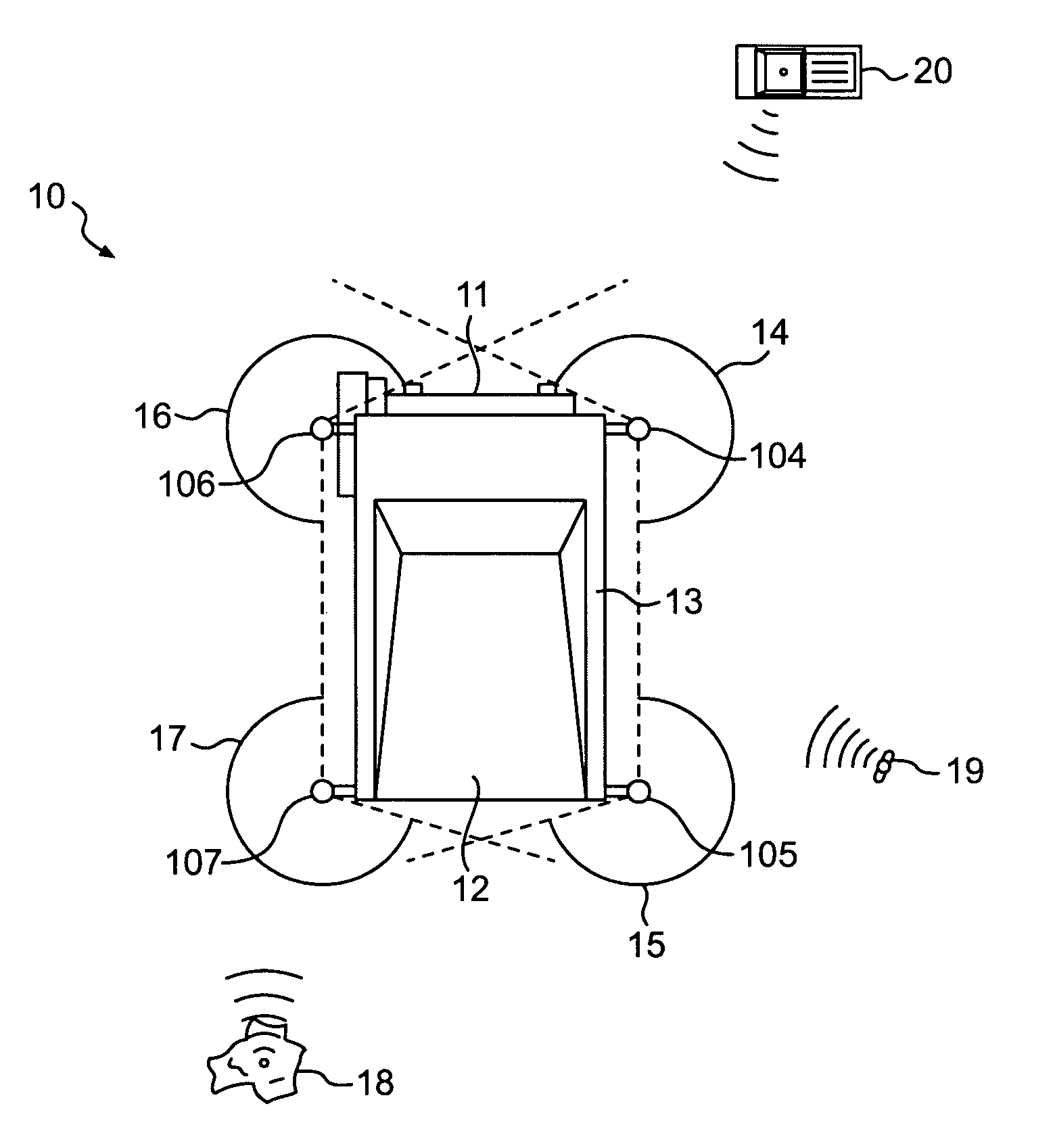
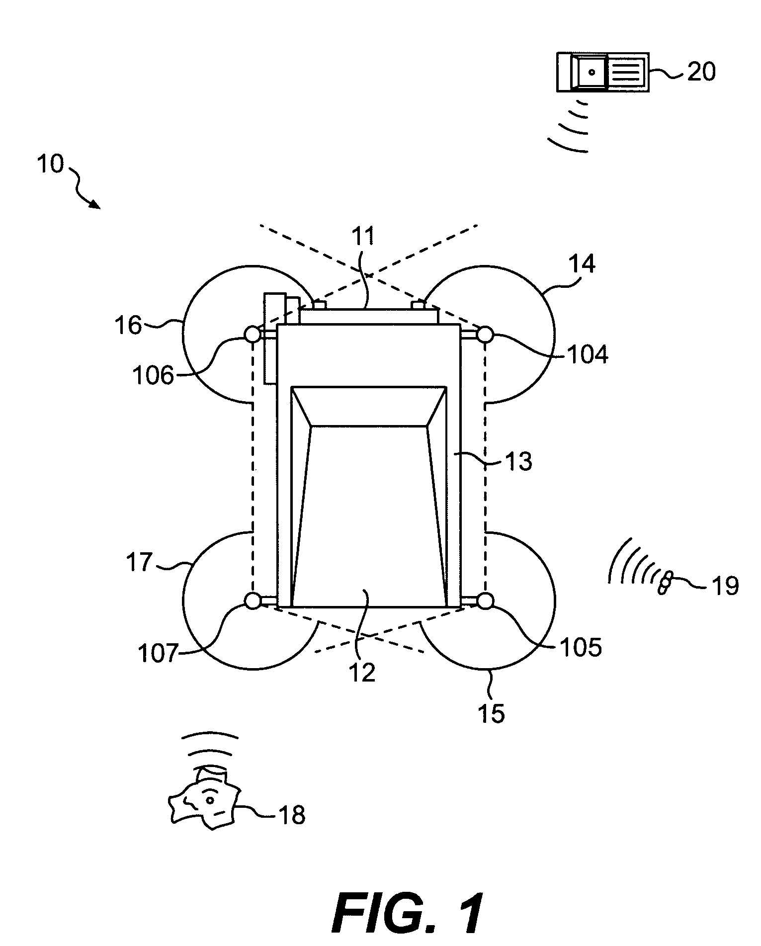
[0017]FIG. 1 provides a schematic top-view illustration of a work machine 10 according to an exemplary disclosed embodiment. Work machine 10 may include a truck, wheel loader, track-type tractor, wheeled tractor, vehicle, or any other type of machine known in the art. As used herein the terms “vehicle,”“machine,” and “equipment” are interchangeable, and by way of non-limiting examples, may refer to any equipment that may be used in any vehicular, construction, mining, work site, or other machine-related capacity.

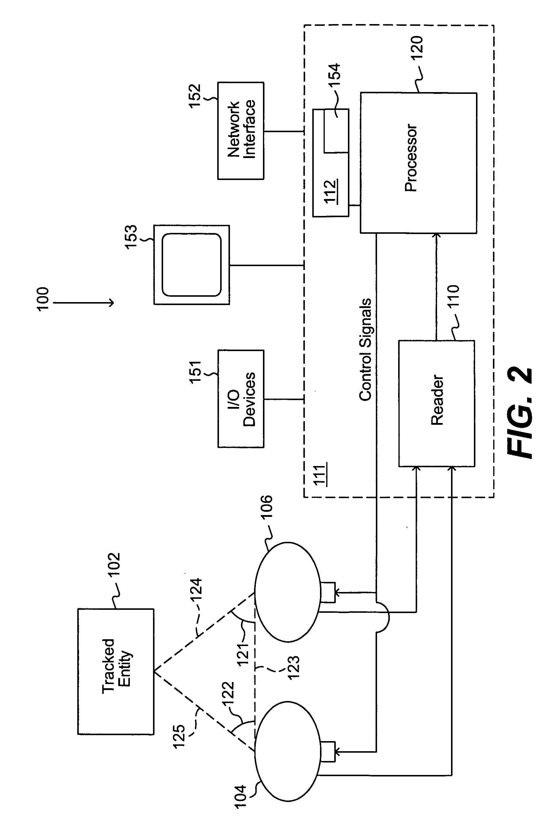
[0018] As illustrated in FIG. 1, work machine 10 may include a dump truck having a front end 1 and a load carrying area 12. Work machine 10 may also include a body 13 onto which an array of tracking antennas may be mounted. These tracking antennas can be included as part of a tracking system, which will be discussed in more detail below. Work machine 10 may include a first antenna 104 and a second antenna 106 used for tracking the locations of various entities at a work sit...


PUM


Abstract

A system for tracking entities at a work site includes an antenna having a scanned boresight. A controller may be configured to determine a relative angle between a reference associated with the antenna and a source of radiation based on a relationship between boresight orientation and relative power values of a signal received by the antenna from the source of radiation for two or more boresight orientations of the antenna.

Description

[0001] This application claims the benefit of U.S. Provisional Application No. 60 / 523,503, filed Nov. 18, 2003, which is incorporated herein by reference.TECHNICAL FIELD [0002] The present disclosure relates to the field of work site management systems and methods, and more particularly, to systems and methods for tracking entities at a work site. BACKGROUND [0003] Workers at work sites, including construction and / or mining sites, may experience dangers from several elements. For example, these sites typically include heavy machinery and equipment, such as bulldozers, cranes, front wheel loaders, soil stabilizers, rippers, and pulverizers. Operators of such heavy machinery and equipment often have a limited field of vision and may not readily detect the presence of other entities (e.g., workers, structures, and / or other machines) at the work site. The lack of knowledge regarding the presence and location of workers and other machines at the work site can lead to accidental collision...

Claims


Application Information

Patent Timeline
IPC IPC(8): B66C15/04G01S19/09G01S13/74G01S13/75G01S13/87G01S19/48G08B21/00
CPCB66C15/045G01S13/878G01S13/75G01S13/74
Inventor GUDAT, ADAM J.
Owner CATERPILLAR INC
Why Eureka
Try Eureka