
Active camera video-based surveillance systems and methods

a technology of video-based surveillance and active cameras, applied in the direction of television systems, direction/deviation determining electromagnetic systems, instruments, etc., can solve the problems of inaccuracy, often too slow to catch the target, and require computational power, so as to improve the quality of information

Inactive Publication Date: 2005-05-19
OBJECTVIDEO
View PDF27 Cites 251 Cited by
  • Summary
  • Abstract
  • Description
  • Claims
  • Application Information

AI Technical Summary

Benefits of technology

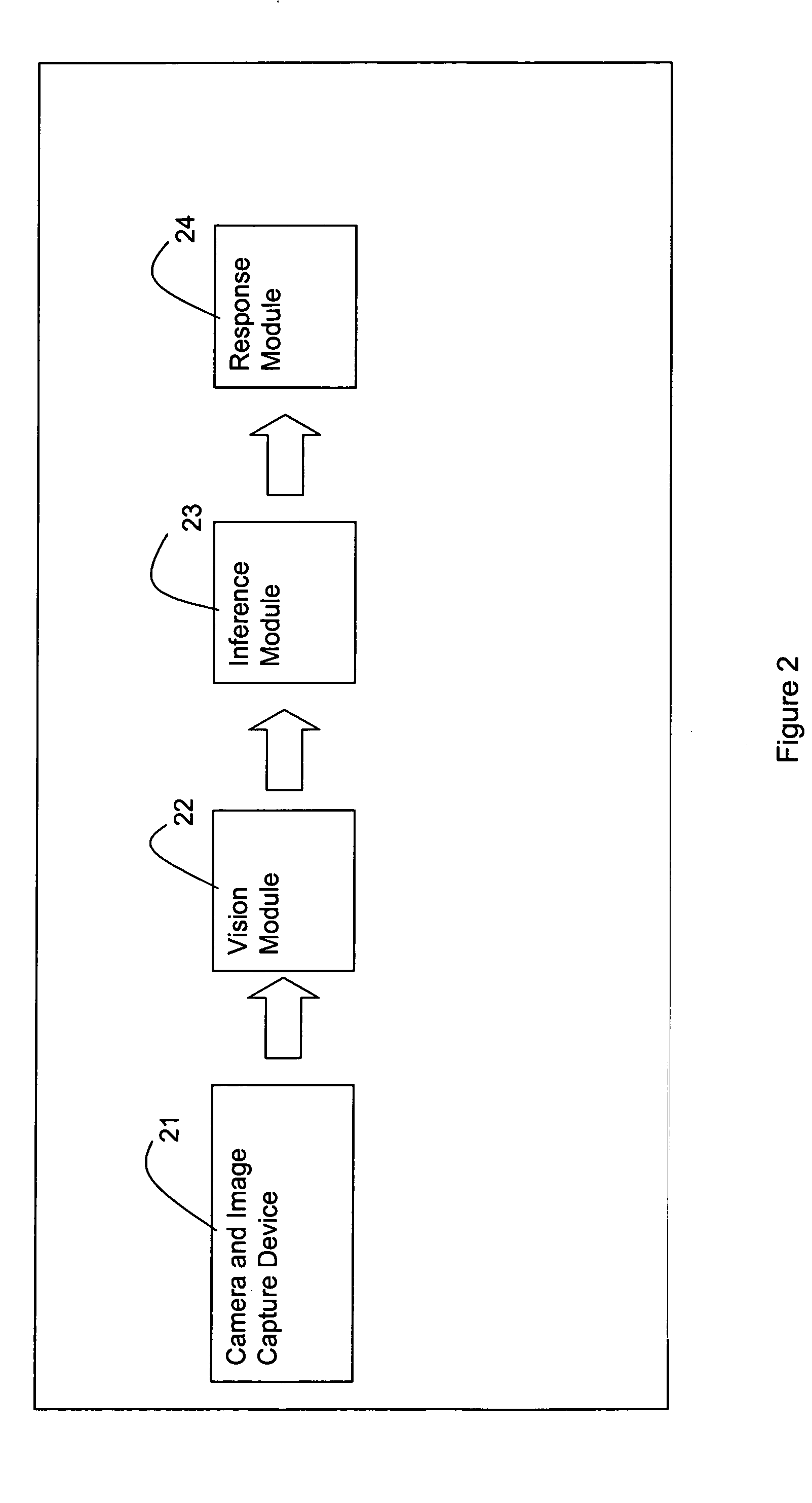
[0006] According to another embodiment, the invention may comprise a method of operating a video surveillance system, the video surveillance system including at least one sensing unit capable of being operated in first and second modes. The method of this embodiment may comprise: operating a sensing unit in the first mode to scan for targets; processing image data from the sensing unit in a first mode to detect the presence of an interesting target; upon detecting an interesting target, operating the sensing unit in the second mode to track the interesting target and to improve the quality of information about the interesting target over the information that can be obtained in the first mode; and processing image data from the sensing unit in a second mode to track the target by sending at least one of pan, tilt, and zoom commands to the sensing unit. The method of this embodiment may be implemented as software on a computer-readable medium. Furthermore, the invention may be embodied in the form of a computer system running such software.

Problems solved by technology

However, a typical purchaser of a security system may be driven by cost considerations to install as few sensing devices as possible.
The problem, however, is that such systems require a human operator to recognize the target and to train the PTZ sensing device on the recognized target, a process which is inaccurate and often too slow to catch the target.
The problem with these methods is that they either require computational power that would prohibit normal operation or require a different sensing modality that would disturb normal operation.

Method used


Image

  • Active camera video-based surveillance systems and methods
  • Active camera video-based surveillance systems and methods
  • Active camera video-based surveillance systems and methods

Examples


Embodiment Construction

Overall System

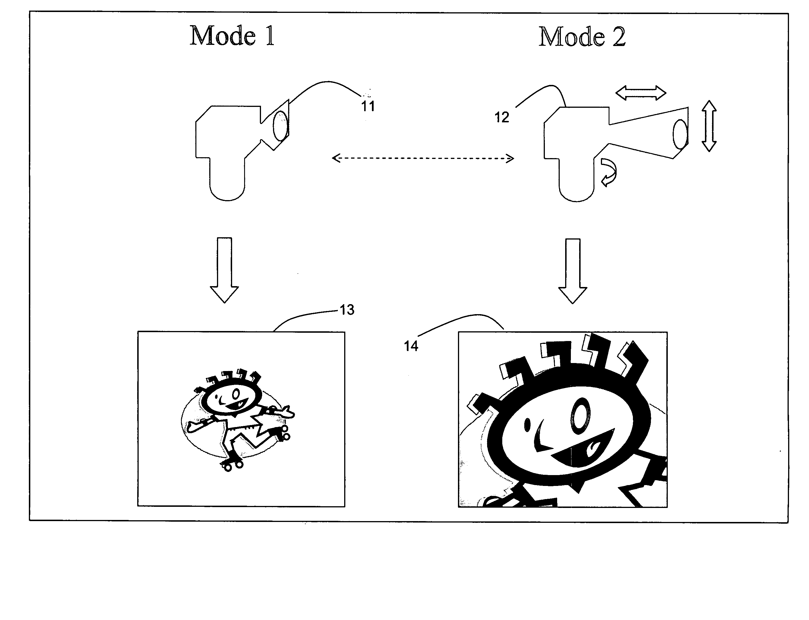
[0036]FIG. 1 depicts a conceptual embodiment of the invention using cameras 11 and 12; in the present invention, these cameras 11 and 12 are implemented using a single camera (as indicated by the dashed arrow between cameras 11 and 12). The system of FIG. 1 uses a camera 11 in one mode to provide an overall picture of the scene 13, and camera 12 in a second mode to provide high-resolution pictures of targets of interest 14. In this embodiment, the combination of cameras 11 and 12 will typically comprise a camera with a zoom lens and pan-tilt-zoom (PTZ) means, allowing the camera to be positioned as needed to obtain high-resolution pictures of the target 14 when such target is detected by the camera operating in a wide-angle mode (with or without panning).

[0037] The camera of the present invention may, for example, comprise a video camera (or other video sensing device) having a motorized zoom lens and a motorized platform that allows the camera to pan and / or tilt. T...


PUM


Abstract

A video surveillance system comprises a sensing unit capable of being operated in a first mode and second mode and a computer system coupled to the sensing unit. The computer system is adapted to receive and process image data from the sensing unit, to detect and track targets, and to determine whether the sensing unit operates in the first mode or in the second mode based on the detection and tracking of targets.

Description

FIELD OF THE INVENTION [0001] The present invention is related to methods and systems for performing video-based surveillance. More specifically, the invention is related to such systems involving multiple interacting sensing devices (e.g., video cameras). BACKGROUND OF THE INVENTION [0002] Many businesses and other facilities, such as banks, stores, airports, etc., make use of security systems. Among such systems are video-based systems, in which a sensing device, like a video camera, obtains and records images within its sensory field. For example, a video camera will provide a video record of whatever is within the field-of-view of its lens. Such video images may be monitored by a human operator and / or reviewed later by a human operator. Recent progress has allowed such video images to be monitored also by an automated system, thus saving the human labor. [0003] In many situations, for example, if a robbery is in progress, it would be desirable to detect a target (e.g., a robber)...

Claims


Application Information

Patent Timeline
IPC IPC(8): G01S3/786G06K9/00G08B13/194H04N7/18
CPCG01S3/7864G06K9/00771G08B13/19602H04N7/18G08B13/19608G08B13/19689G08B13/19697G08B13/19604G06V20/52
Inventor EGNAL, GEOFFREYCHOSAK, ANDREWHAERING, NIELSLIPTON, ALAN J.VENETIANER, PETER L.YIN, WEIHONGZHANG, ZHONG
Owner OBJECTVIDEO
Learn More