Method and apparatus for aiding image interpretation and computer-readable recording medium storing program therefor

a technology of image interpretation and computer-readable recording medium, which is applied in the field of method and apparatus for aiding image interpretation, can solve the problems of reducing alignment accuracy, time-consuming process, and more apparent description problems, and achieve the effect of suppressing artifacts in subtraction images and improving alignment accuracy

a technology of image interpretation and computer-readable recording medium, which is applied in the field of method and apparatus for aiding image interpretation, can solve the problems of reducing alignment accuracy, time-consuming process, and more apparent description problems, and achieve the effect of suppressing artifacts in subtraction images and improving alignment accuracy

US20050105828A1Inactive Publication Date: 2005-05-19FUJIFILM HLDG CORP +1

Image

  • Method and apparatus for aiding image interpretation and computer-readable recording medium storing program therefor
  • Method and apparatus for aiding image interpretation and computer-readable recording medium storing program therefor
  • Method and apparatus for aiding image interpretation and computer-readable recording medium storing program therefor

Examples


first embodiment

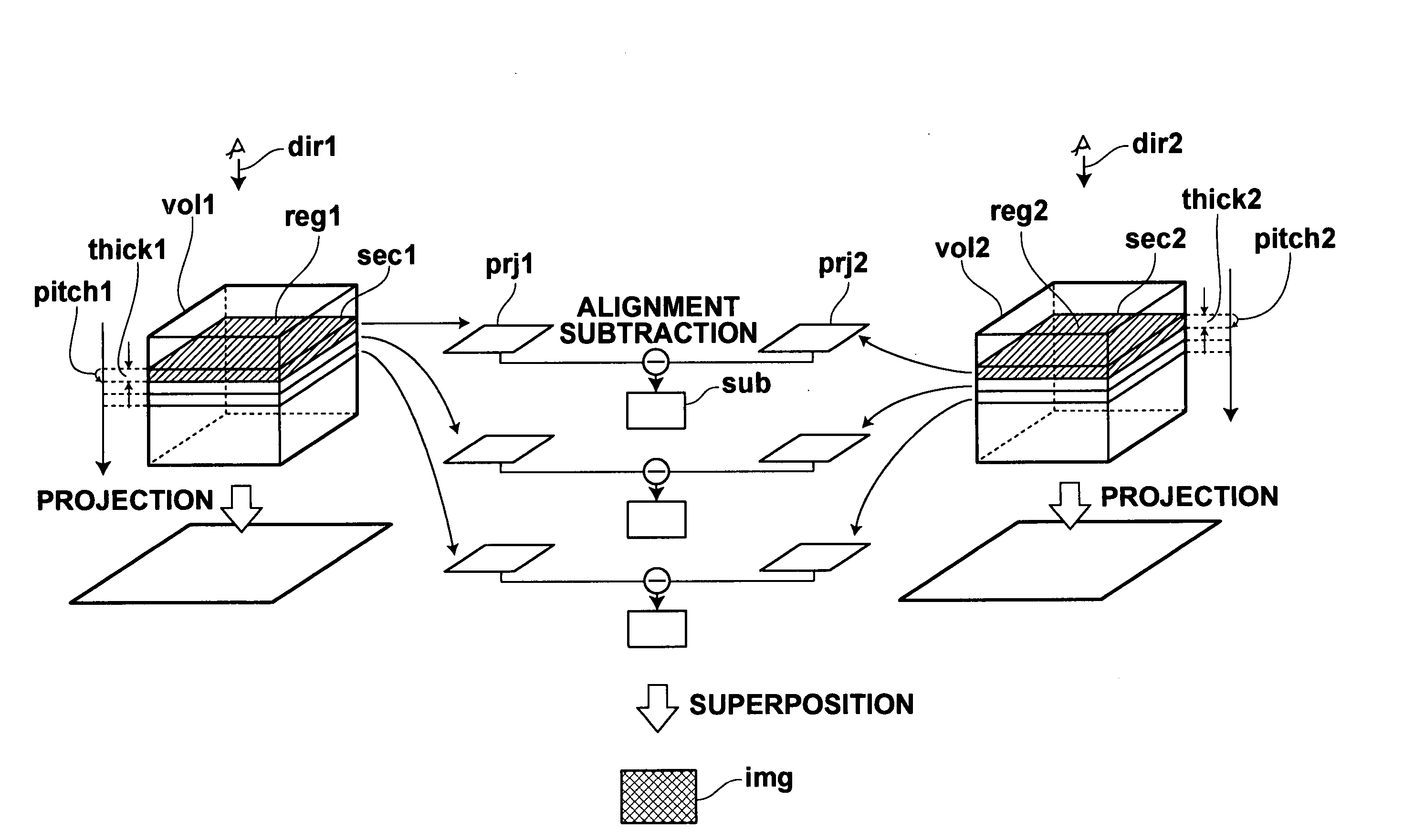
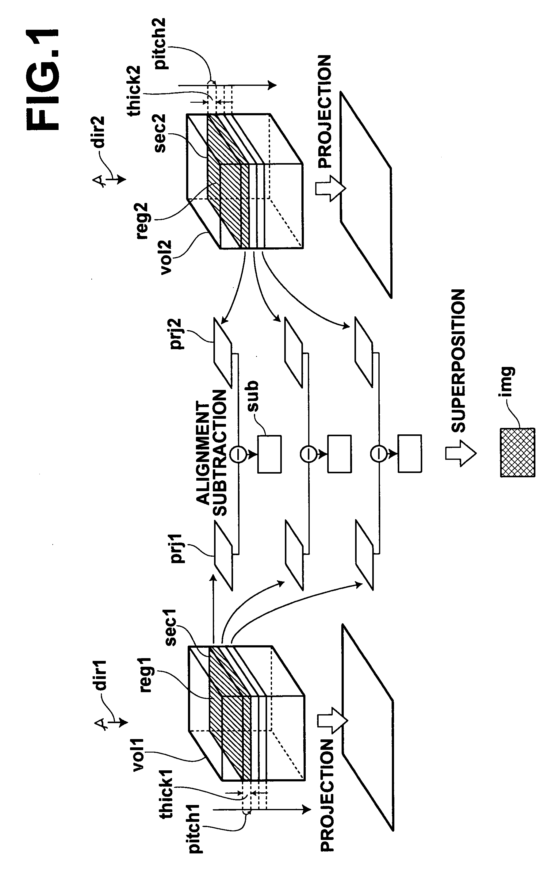
[0091] The image interpretation aiding apparatus 101 of the present invention generates projection images by projecting pixels in regions specified by cross sections and thicknesses in two CT images representing the same subject but photographed at different times. The image interpretation aiding apparatus 101 then aligns lung fields in the projection images corresponding to each other, and generates subtraction images. The image interpretation aiding apparatus 101 further generates a superposed subtraction image by superposing the subtraction images. (In the explanation below, an image represented by an image data set has the same reference number as the image data set. For example, an image represented by an image data set Y1 is referred to as an image Y1).

[0092]FIG. 7 is a block diagram showing the configuration of the image interpretation aiding apparatus 101 and peripheral systems, and flows of data. As shown in FIG. 7, the image interpretation aiding apparatus 101 comprises: [...

second embodiment

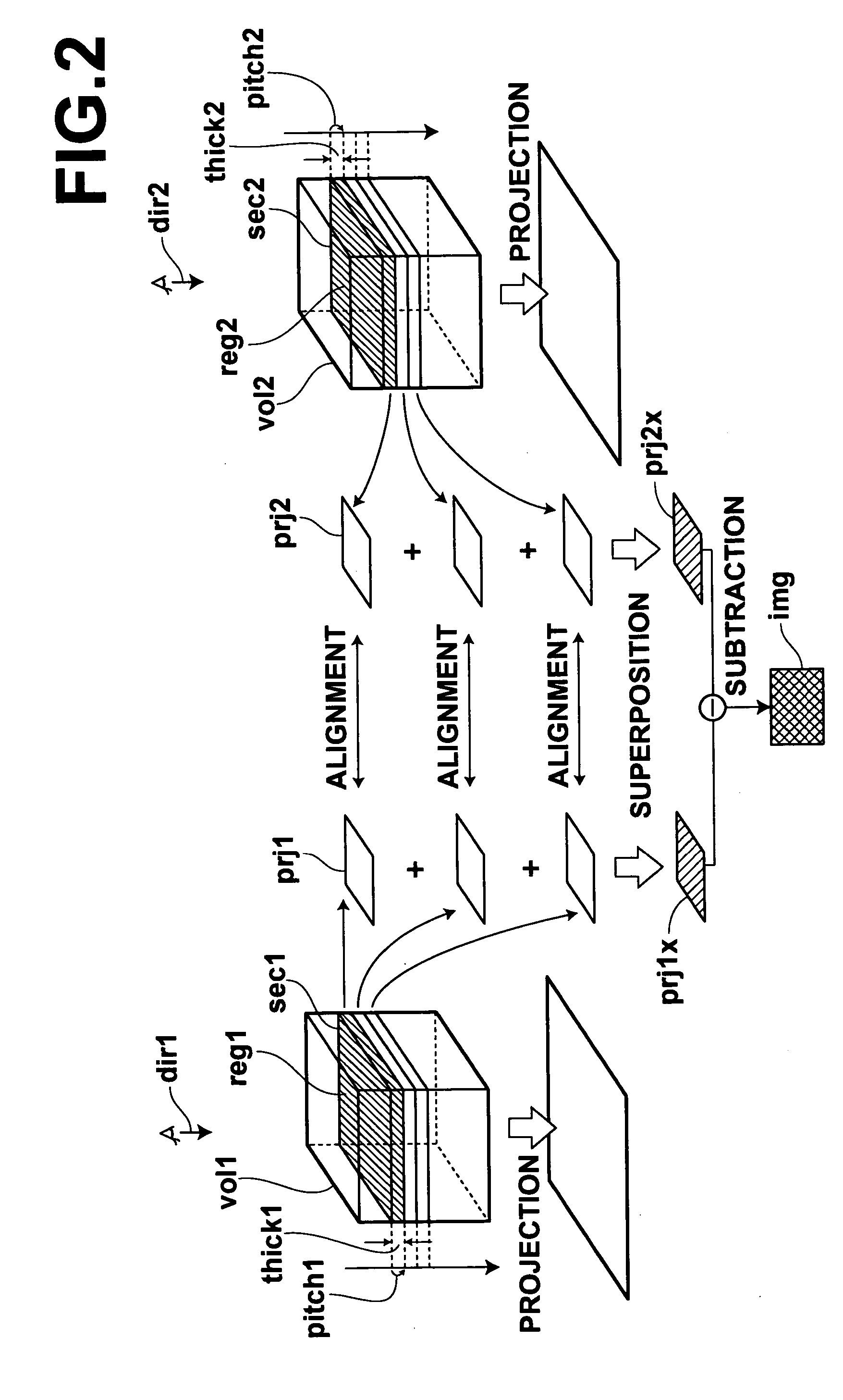
[0136] An image interpretation aiding apparatus 102 of the present invention will be described next. The image interpretation aiding apparatus 102 generates the projection images by projecting the pixels in the regions specified by the cross sections and the thicknesses in the two CT images representing the same subject but photographed at different times. The image interpretation aiding apparatus 102 then carries out alignment processing on lung fields in the projection images corresponding to each other, and carries out superposition processing on the projection images of the respective CT images having been subjected to the alignment processing. The image interpretation aiding apparatus 102 then generates the superposed subtraction image, based on a difference between the two projection images having been subjected to the superposition processing.

[0137]FIG. 16 is a block diagram showing a configuration of the image interpretation aiding apparatus 102 and peripheral systems, and f...


PUM


Abstract

In comparative image reading of projection images representing an observation target in two three-dimensional images of the same subject photographed at different times, alignment accuracy can be improved between the projection images and artifacts in subtraction images can be suppressed. In each of the three-dimensional images, pixels in a region specified by a cross section perpendicular to an observation direction and a thickness are projected, and the projection images are generated by repeating the procedure while moving a position of the cross section in the observation direction. Alignment processing and subtraction image generation is carried out between the corresponding projection images, and a superposed subtraction image is generated by superposing the generated subtraction images. Consequently, an effect of three-dimensional body movement of the subject at the time of photography can be suppressed than a projection image generated by projecting the entire observation target.

Description

BACKGROUND OF THE INVENTION [0001] 1. Field of the Invention [0002] The present invention relates to a method and an apparatus for aiding image interpretation, and to a computer-readable recording medium storing a program therefor. More specifically, the present invention relates to a method and an apparatus for aiding comparative image reading between two projection images by aligning projection images generated from two three-dimensional images representing the same subject photographed at different times, and to a computer-readable recording medium storing a program therefor. [0003] 2. Description of the Related Art [0004] Inspection of a subject has been carried out in various fields, based on comparison of a difference between two or more images thereof. For example, in the field of manufacturing, an image of a product photographed at the time of production thereof is compared with an image thereof obtained after endurance tests thereon. A part showing a substantial difference ...

Claims


Application Information

Patent Timeline
19 May 2005
Publication
US20050105828A1
IPC
A61B6/03; G06K9/32; G06T7/00; G06T17/40; H05G1/64
CPC
A61B6/032; A61B6/5264; G06T7/0038; G06T2219/028; G06T2207/30004; G06T2210/41; G06T19/00; G06T7/38
Inventors
OOSAWA, AKIRA