Turbine wheel for turbomachine and the assembly method for such a wheel

Active Publication Date: 2005-05-19
SN DETUDE & DE CONSTR DE MOTEURS DAVIATION S N E C M A
View PDF6 Cites 11 Cited by
  • Summary
  • Abstract
  • Description
  • Claims
  • Application Information

AI Technical Summary

Benefits of technology

[0021] Thus, regardless of the configuration adopted for the turbine wheel according to the invention, the turbine wheel generates almost no restriction about the maximum number of blades to be provided on each segment. Consequently, this considerably reduces the number of these blade segments, and therefore also the number of spaces to be sealed between two directly consecutive blade segments, compared with the number used in the embodiments according to prior art. Therefore, global sealing of the turbine wheel is naturally significantly improved.
[0031] Still preferably, each blade segment also comprises holding means for maintaining permanent cooperation between the upstream and downstream engagement means of the blade segment installed on the turbine disk, and the corresponding complementary upstream and downstream engagement means of this turbine disk, when they cooperate with the turbine disk. In this way, permanent cooperation between the various engagement means advantageously provides the means of holding the blade segments fixed with respect to the turbine disk and therefore obtaining precise radial and circumferential indexing of each of these blade segments with respect to the turbine disk.

Problems solved by technology

Although this solution is very widespread in turbines in existing turbomachines, it thus has a number of serious disadvantages.
Naturally, these large volumes directly result in weight constraints and material cost constraints.
Note also that the complex production of > shapes of blades and the disk causes non-negligible manufacturing costs.
Furthermore, with this type of solution according to prior art, it is obvious that a given root cannot support a large number of blades, and the number of blades is usually less than or equal to two.
In this respect, and as occurs in prior art, the fact that it is impossible to make segments fitted with a significant number of blades, and therefore to design long segments in the circumferential direction, is a major disadvantage.
Moreover, this type of embodiment does not enable a satisfactory seal between firstly the turbine disk and secondly the blade segments.
However, the required upstream labyrinth is a large part with a high mass and is extremely complicated to make, such that its presence is a very serious disadvantage, particularly in terms of extra cost.

Method used


Image

  • Turbine wheel for turbomachine and the assembly method for such a wheel
  • Turbine wheel for turbomachine and the assembly method for such a wheel
  • Turbine wheel for turbomachine and the assembly method for such a wheel

Examples


Embodiment Construction

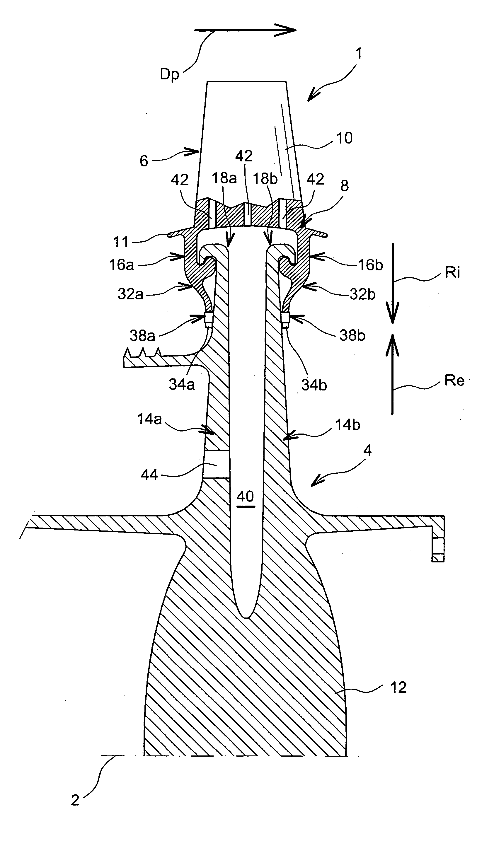
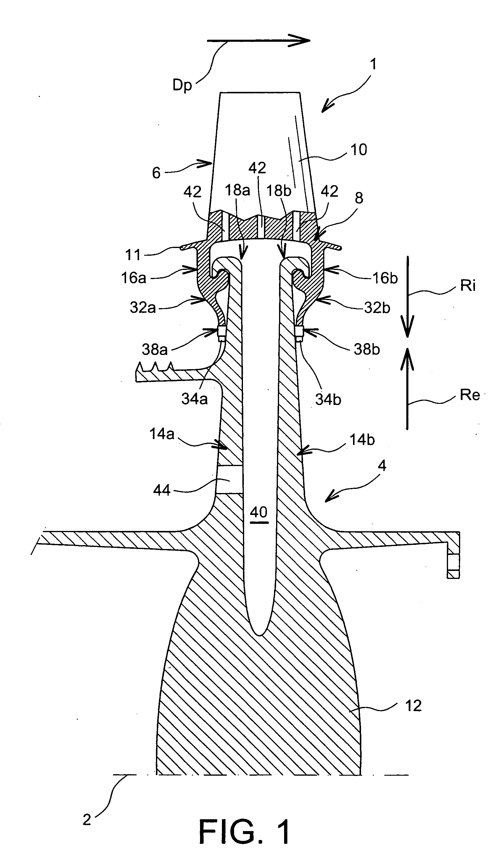
[0049] A turbine wheel 1 for a turbine machine according to a first preferred embodiment of this invention is shown with reference jointly to FIGS. 1 and 2.

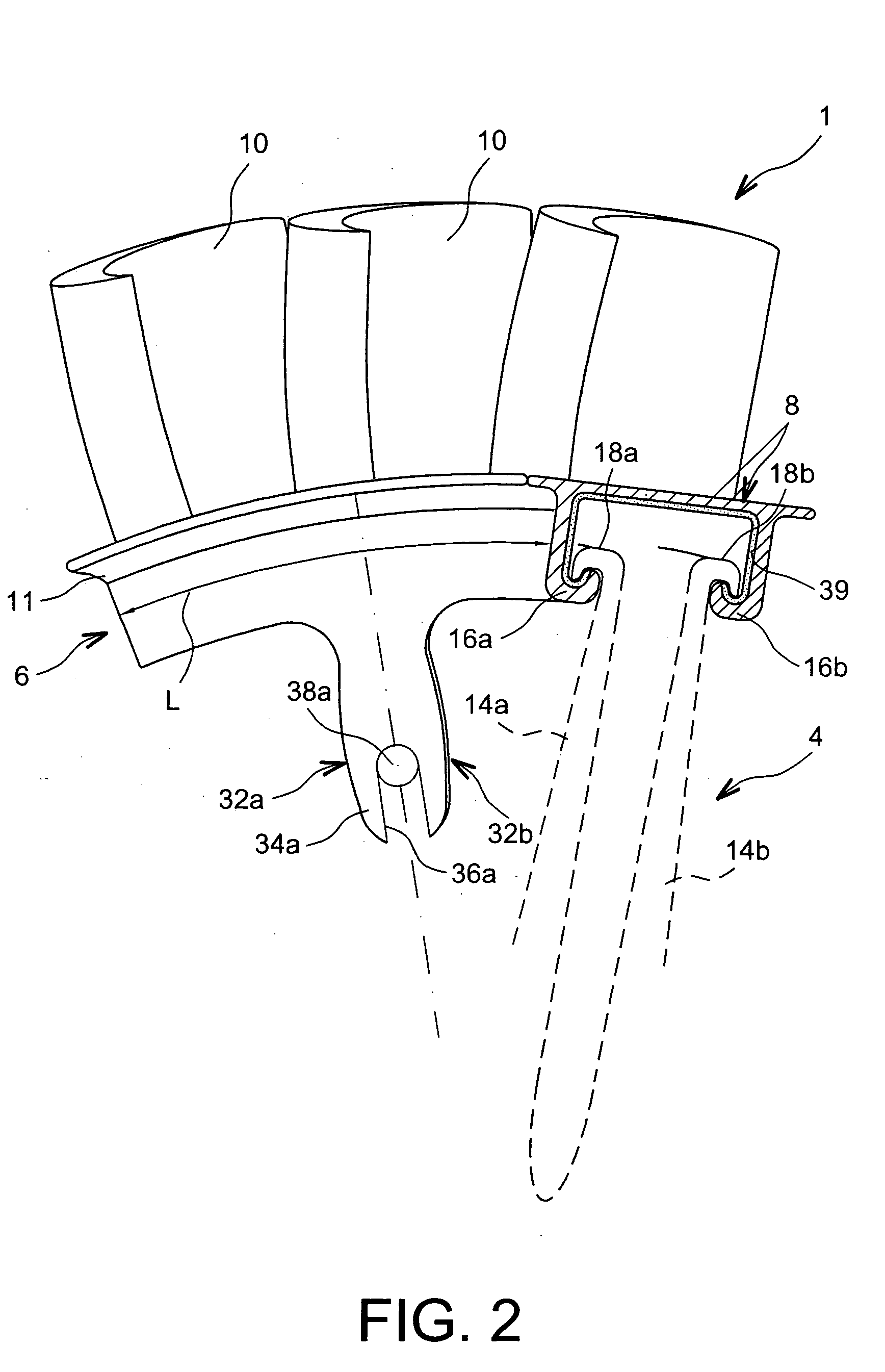
[0050] The turbine wheel 1, with a longitudinal principal axis 2, comprises a turbine disk 4, preferably single-piece, and several blade segments 6 installed on the disk 4, only one of these segments 6 being shown in FIG. 2.

[0051] Each blade segment 6 comprises a root 8 prolonged in the radial direction outwards by a blade 10, or preferably by several blades 10. For example, each segment 6 is provided with three blades 10 fixed to an external radial part 11 of the root 8, for example this part 11 of the metallic plate type possibly with a variable thickness may be approximately in the shape of an angular sector of a cylindrical geometry with an axis identical to the longitudinal principal axis 2. Furthermore, the turbine wheel may be designed so as to have about twenty segments 6 of three blades 10, these segments 6 being unifo...


PUM


Abstract

The invention relates to a turbine wheel (1) for a turbomachine, the disk (4) of which comprises upstream and downstream ribs (14a, 14b) extending in the annular direction around an axis (2), each blade segment (6) installed on the disk possibly being retained by the disk in an external radial direction using upstream engagement means (16a) forming part of the segment root (8) and capable of cooperating with complementary upstream engagement means (18a) forming an external radial end of the upstream rib, and downstream engagement means (16b) forming part of the root and capable of cooperating with complementary downstream engagement means (18b) forming an external radial end of the downstream rib. Furthermore, the upstream and downstream ribs are designed so that they can be moved from a separated engagement position to a close position, and vice versa, so that each blade segment can be assembled on the turbine disk.

Description

TECHNICAL DOMAIN [0001] This invention generally relates to a turbine wheel for a turbomachine, of the type comprising a turbine disk and several blade segments installed on this turbine disk. [0002] Furthermore, the invention also relates to an assembly method for such a turbine wheel. STATE OF PRIOR ART [0003] Conventionally, as known in prior art, a turbine wheel for a turbomachine comprises a turbine disk and several blades installed on the turbine disk, each blade comprising a root extending from a radially inner profile, and being provided with retaining shapes known as <<ribbed fittings>>. [0004] To assemble the blades on a turbine disk, the turbine disk is usually provided with a series of approximately axial grooves opened radially towards the outside, with a shape complementary to the shape of the above mentioned <<ribbed fittings>>, and in which the blades may be inserted one after the other, to be held in place by this turbine disk. [0005] Althoug...

Claims


Application Information

Patent Timeline
IPC IPC(8): F01D5/00F01D5/02F01D5/30
CPCF01D5/00F01D5/3069F01D5/3046F01D5/3023
Inventor LARDELLIER, ALAIN
Owner SN DETUDE & DE CONSTR DE MOTEURS DAVIATION S N E C M A
Why Eureka
Try Eureka