
Image-receiving element

a technology of image-receiving element and strip-coat, which is applied in the direction of diffusion transfer process, instruments, photosensitive materials, etc., can solve the problems of reducing the effectiveness of facilitation, strip-coat may produce a noticeable haze over the image-receiving element, and progressively thinner strip-coats

Inactive Publication Date: 2005-05-19
SENSHIN CAPITAL
View PDF10 Cites 20 Cited by
  • Summary
  • Abstract
  • Description
  • Claims
  • Application Information

AI Technical Summary

Benefits of technology

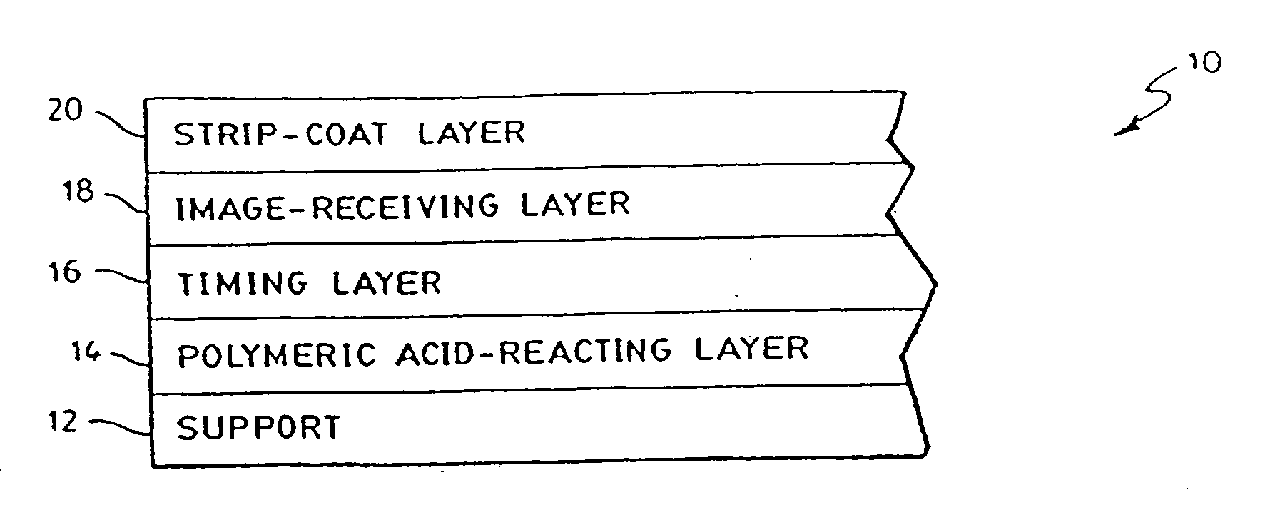
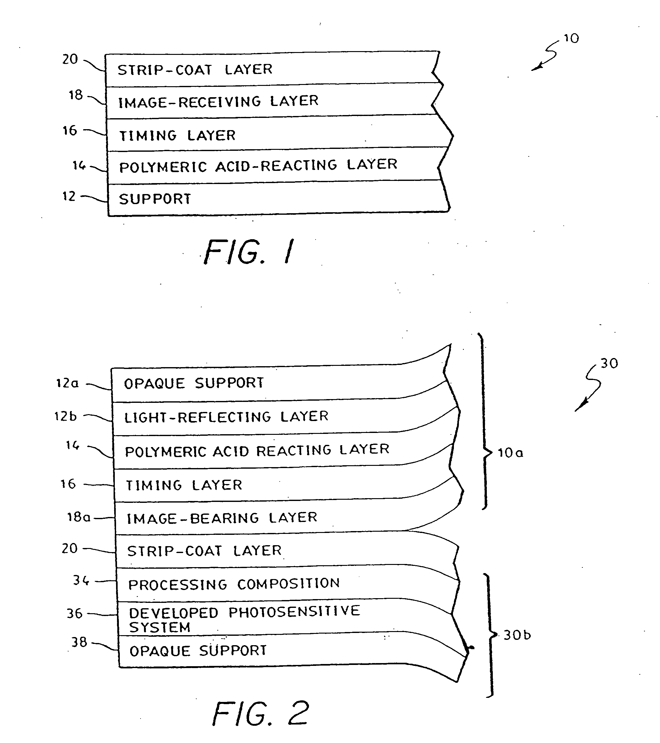
"The present invention is about an image-receiving element used in photographic and photothermographic film units. It consists of a support, an image-receiving layer, and a strip-coat layer. The strip-coat layer is made of a mixture of poly(acrylic acid) and a cationic quaternary salt. The quaternary salt can also be associated with a photographically acceptable anion. The poly(acrylic acid) has a molecular weight of 5,000 to 250,000 and a ratio of poly(acrylic acid) to quaternary salt of 5:1 to 1:1. The strip-coat layer also includes an ethoxylated alcohol to prevent unwanted bonding at high humidity. The technical effect of this invention is to improve the quality and stability of the image-receiving element in photographic and photothermographic film units."

Problems solved by technology

Some strip-coats may produce a noticeable haze over the image-receiving element upon processing and separation from the photosensitive element.
However, a drawback to providing progressively thinner strip-coats is a reduced effectiveness in facilitating separation between the photosensitive element and the image receiving element.
Furthermore, in photographic embodiments, processing composition often remains adhered to thinner strip-coats after processing and separation from the photosensitive element, thus detracting from the quality of the resulting image.

Method used


Image

  • Image-receiving element
  • Image-receiving element
  • Image-receiving element

Examples


examples

[0045] The invention will now be described further in detail with respect to specific preferred embodiments by way of examples, it being understood that these are intended to be illustrative only and the invention is not limited to the materials, conditions, process parameters, etc. recited therein. All parts and percentages recited are by weight unless otherwise stated.

example i

[0046] Diffusion transfer photographic film units A-D according to the invention were prepared wherein the image-receiving element comprised the following layers deposited in succession upon an opaque polyethylene clad paper support: [0047] 1. a polymeric acid-reacting layer at a coverage of about 25,609 mg / m2 (2380 mg / ft2), comprising 9 parts GANTREZ S-97 (a free acid of a copolymer of methyl vinyl ether and maleic anhydride available from the GAF Corp.), and 11 parts AIRFLEX 465 (a vinyl acetate ethylene latex available from the Air Products Co.), and about 2% by weight (based on the amount of Gantrez) of hexamethylmethoxymelamine; [0048] 2. a timing layer coated at a coverage of 4844 mg / m2 (450 mg / ft2) of a 29 / 14.9 / 43 / 10 / 3.2 (parts by weight) pentapolymer of butyl acrylate, methyl methacrylate, diacetone acrylamide, carbomethoxymethyl acrylate and acrylic acid; [0049] 3. an image-receiving layer coated at a coverage of about 3228 mg / m2 (300 mg / ft2) comprising: 2 parts of a terpol...


PUM

PropertyMeasurementUnit
thicknessaaaaaaaaaa
thicknessaaaaaaaaaa
relative molar ratiosaaaaaaaaaa

Abstract

An image-receiving element for use in photographic and photothermographic diffusion transfer film units of the type where the image-receiving element is designed to be removed, or “peeled-apart” from a photosensitive element following exposure and photographic processing. The present image-receiving element comprises, in sequence, a support, an image-receiving layer and a strip-coat layer which serves to facilitate separation of the image-receiving element from the photosensitive element after photographic processing. The strip-coat layer comprises an anion of poly(acrylic acid), or a salt thereof, complexed with a cationic quaternary salt. In a preferred embodiment, the strip coat layer may include an ethoxylated alcohol.

Description

BACKGROUND OF THE INVENTION [0001] This invention relates to an image-receiving element for use in photographic and photothermographic film units of the diffusion transfer type. More particularly, the invention relates to an image-receiving element especially adapted for use in diffusion transfer film units wherein an image-receiving element is designed to be separated from a photosensitive element after exposure and processing. [0002] Photographic film units of this type are well known and are often referred to as “peel apart” photographic film units. Various embodiments of peel-apart film units are known and include those wherein images are formed in black and white (reduced silver), and color (image dyes), as described in: E. H. Land, H. G. Rogers, and V. K. Walworth, in J. M. Sturge, ed., Neblette's Handbook of Photography and Reprography, 7th ed., Van Nostrand Reinhold, New York, 1977, pp. 258-330; and V. K. Walworth and S. H. Mervis, in J. Sturge, V. Walworth, and A. Shepp, ed...

Claims


Application Information

Patent Timeline
Patent Type & Authority Applications(United States)
IPC IPC(8): G03C8/40G03C8/50G03C8/52
CPCG03C8/4046G03C8/52G03C8/50
Inventor GOMES, GERARDLAPOINTE, GARY S.MANNING, JAMES J.
Owner SENSHIN CAPITAL
Learn More