Press-contact connector built in substrate

a technology of substrate and contact connector, which is applied in the direction of contact members penetrating/cutting insulation/cable strands, coupling device connections, electrical apparatus, etc., can solve the problems of connector housing bending, electrical connector containing circuit boards, and not being provided, etc., to achieve the effect of reliably absorbing the load of insulation displacemen

Inactive Publication Date: 2005-05-19
JST MFG CO LTD
View PDF7 Cites 25 Cited by
  • Summary
  • Abstract
  • Description
  • Claims
  • Application Information

AI Technical Summary

Benefits of technology

[0015] this drawing load does not have influence upon the insulation displacement connecting portions, so that the reliability of electrical connection can be greatly heightened.
[0032] According to this invention, the leads of a simple construction can reliably absorb the insulation displacement load.

Problems solved by technology

However, an electric connector containing a circuit board, wherein an insulation displacement terminal soldered to the circuit board is connected by insulation displacement with an electric wire within a connector housing, has not ever been provided.
When the terminal is connected by insulation displacement with the electric wire within the connector housing, there is a fear that the connector housing is bent due to an insulation displacement load imparted to the terminal, and that a portion where the terminal is soldered to the circuit board is broken due to the load.
However, when a drawing force is exerted from the outside on insulated wires, there is a fear that the connecting force of the insulation displacement terminals is lessened.
In addition, since the insulation displacement terminals soldered to the circuit board in advance come to be connected by insulation displacement with the electric wires, therefore, there is the possibility that the soldered portions are broken when the terminals are connected by insulation displacement with the electric wires, or when a drawing load is imparted to the terminals.

Method used


Image

  • Press-contact connector built in substrate
  • Press-contact connector built in substrate
  • Press-contact connector built in substrate

Examples


Embodiment Construction

[0046] A preferred mode of embodiment of the present invention will be described with reference to the attached drawings.

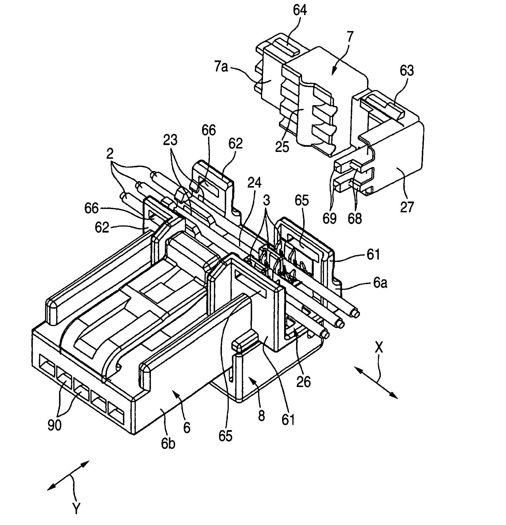
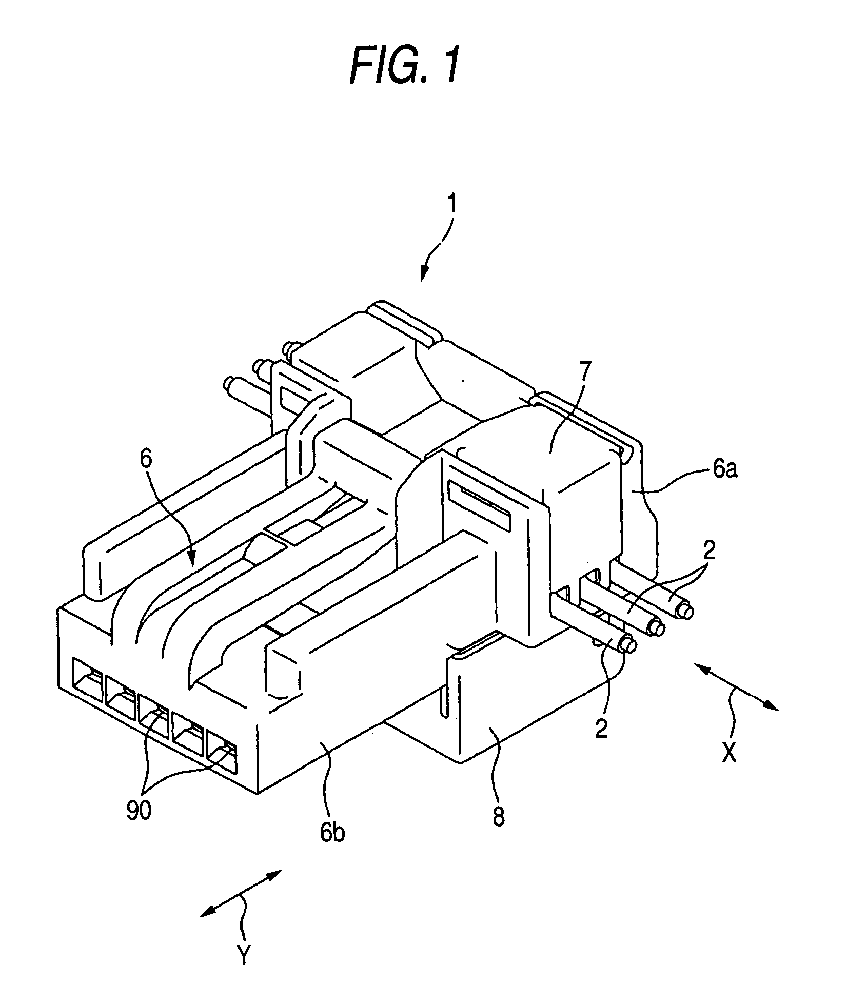
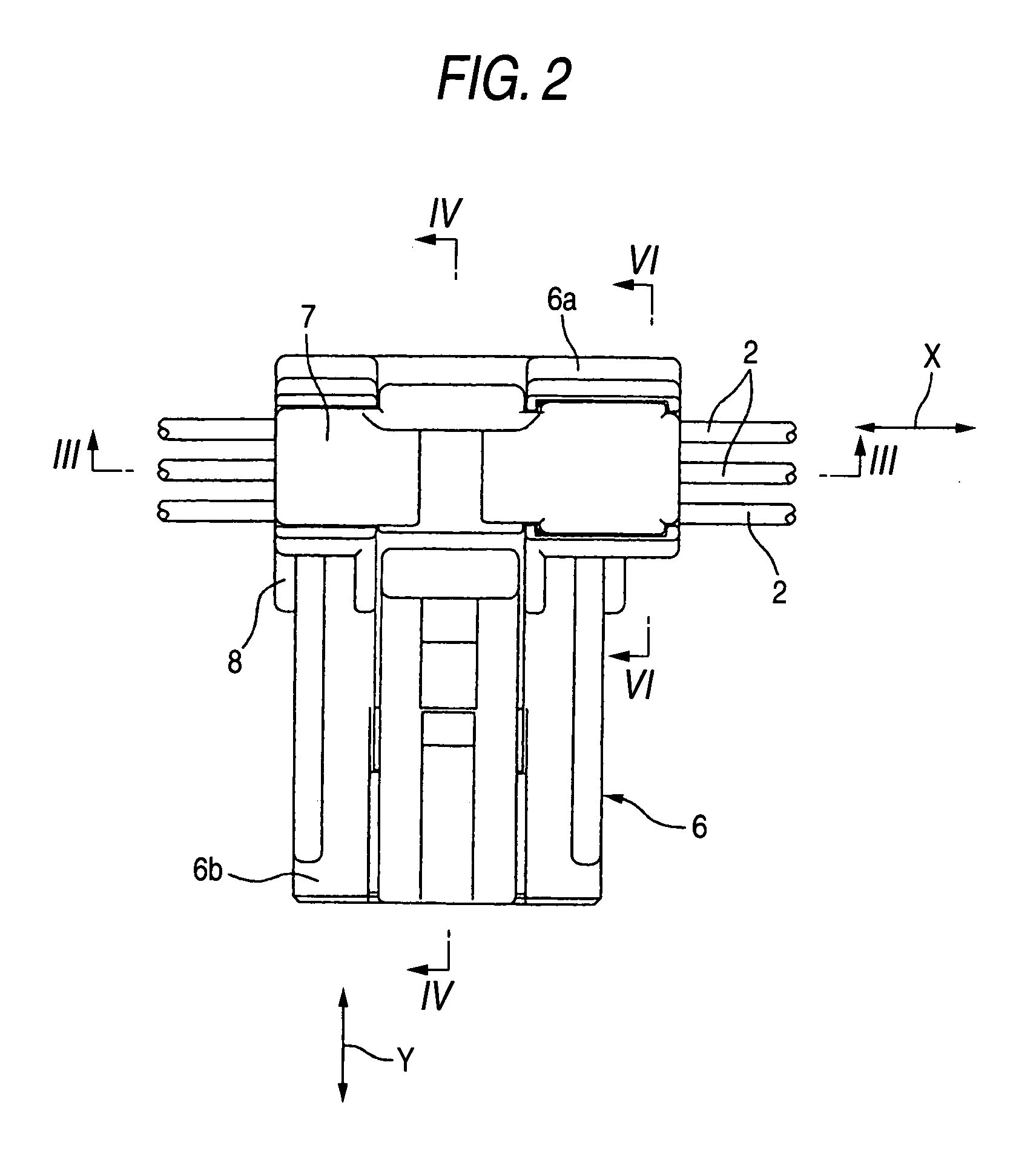
[0047]FIG. 1 is a schematic perspective view of a mode of embodiment of the insulation displacement connector with a built-in board according to the present invention, and FIG. 2 a plan view of the insulation displacement connector with a built-in board. FIG. 3 is a sectional view taken along the line III-III in FIG. 2, and FIG. 4 a sectional view taken along the line IV-IV in FIG. 2.

[0048] Referring to FIG. 1, FIG. 2 and FIG. 3, the insulation displacement connector with a built-in board 1 (which will hereinafter be referred to simply as “connector” as well) is provided with a plurality of insulation displacement terminals 3 (only one insulation displacement terminal is shown in FIG. 3) with which the intermediate portions of a plurality of insulated wires as feed wires extending in the first direction X are connected by insulation displacement, a main housing ...


PUM


Abstract

The insulation displacement terminal 3 is retained on the terminal retainer portion 5 of the main housing 6. The lead 12 of the insulation displacement terminal 3 is soldered to the first surface 10a of the circuit board 10 through the bottom plate 13 of the main housing 6 and the circuit board 10, which is held in the second retaining space 11 between the main housing 6 and second cover housing 8. After the insulation displacement terminal 3 in such a subassembly state is connected by insulation displacement with a desired portion of the insulated wire 2, the first cover housing 7 is combined with the main housing 6. The receiving portion 44 of the second cover housing 8 receives the insulation displacement load via the bottom plate 13 of the main housing 6 and the circuit board 10. This enables the inadvertent bending of the bottom plate 13 and circuit board 10 to be prevented, the reliable insulation displacement connecting of the connector with the insulated wire to be attained, and the so-called in-housing insulation displacement connecting of the connector with the insulated wire to be substantially carried out.

Description

TECHNICAL FIELD [0001] The present invention relates to an insulation displacement connector with a built-in board, containing a circuit board therein and connectable with electric wires by insulation displacement. BACKGROUND ART [0002] In a related art electric connector, there are techniques for connecting an insulation displacement terminal held in a connector housing with electric wire by insulation displacement (refer to, for example, JP-U-06-086261 and JP-A-2000-285994). [0003] Further, an electric connector containing a circuit board has also been provided (refer to, for example, JP-A-2001-297817 and JP-A-2002-067789). [0004] However, an electric connector containing a circuit board, wherein an insulation displacement terminal soldered to the circuit board is connected by insulation displacement with an electric wire within a connector housing, has not ever been provided. [0005] The reasons for this reside in the following. When the terminal is connected by insulation displac...

Claims


Application Information

Patent Timeline
Patent Type & Authority Applications(United States)
IPC IPC(8): H01R4/24H01R13/66
CPCH01R4/2433H01R12/515H01R4/2454H01R4/24H01R9/03
Inventor GOTO, AKIRATAKAGI, YOSHIKAZUMIYAHARA, KAZUSHICHIYODA, MEGUMI
Owner JST MFG CO LTD
Why Eureka
Try Eureka