Liquid ejection head and image forming apparatus including liquid ejection head

a liquid ejection and image forming technology, applied in the direction of printing, inking apparatus, etc., can solve the problems of poor reliability, increased head size, and increased work efficiency in wire bonding, so as to improve reliability, reduce the size of the head, and avoid connection failures

Inactive Publication Date: 2007-09-13
FUJIFILM CORP
View PDF5 Cites 22 Cited by
  • Summary
  • Abstract
  • Description
  • Claims
  • Application Information

AI Technical Summary

Benefits of technology

[0011] The present invention has been contrived in view of these circumstances, an object thereof being to provide a liquid ejection head and a method of manufacturing a liquid ejection head, and to provide an image forming apparatus including this liquid ejection head, whereby the liquid ejection head can be made compact in size, the high density arrangement can be attained, the number of components can be reduced, the reliability of the electrical connections is improved, and high-density wiring can be achieved.

Problems solved by technology

However, in the invention described in Japanese Patent Application Publication No. 2003-182076 mentioned above, since a connection between ICs and a connection between an IC and an electrode are made by wire bonding, then, in a device such as a printer including a drive unit, there is a possibility of disconnection due to vibrations or impacts, and accordingly reliability is poor.
Moreover, since the electrodes to which ICs are connected by wire bonding are provided at the bottom face of a recess shape, then problems arise as to workability and work efficiency in wire bonding.
There is a possibility that the head increases in size.
In the invention described in Japanese Patent Application Publication No. 2005-254616, similarly to the invention of Japanese Patent Application Publication No. 2003-182076, the electrodes to be connected by wire bonding are provided at the bottom surface of a recess shape, and therefore, reliability is poor and problems of work efficiency may arise.

Method used


Image

  • Liquid ejection head and image forming apparatus including liquid ejection head
  • Liquid ejection head and image forming apparatus including liquid ejection head
  • Liquid ejection head and image forming apparatus including liquid ejection head

Examples


first embodiment

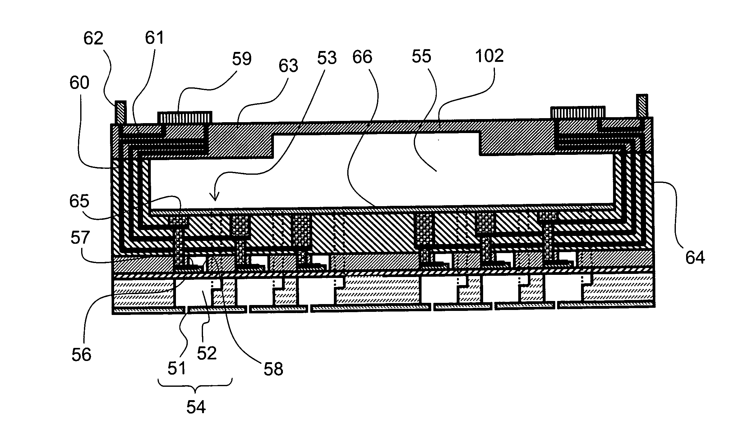
[0079]FIG. 3 is a diagram showing the composition of an inkjet head (liquid ejection head) according to the present invention.

[0080] The walls of a common liquid chamber 55 in the liquid ejection head are formed by a ceramic multi-layer wiring substrate 64 having a recessed shape, and an upper substrate 63 having a substantially planar shape. The upper substrate 63 has a thin section 102 in order to prevent cross-talk between the pressure chamber units. By using a ceramic multi-layer wiring substrate 64 having a recessed shape of this kind, it is possible to reduce the number of connection steps for the electrical wires, and furthermore, it is possible to reduce the number of components. Therefore, reliability can be improved and costs can be reduced, in comparison with the related art. More specifically, the side walls and the bottom surface of the common liquid chamber 55 in the liquid ejection head are constituted by the ceramic multi-layer wiring substrate 64. The ceramic multi-...

second embodiment

[0138] Next, the present invention is described below.

[0139] Below, a liquid ejection head according to the second embodiment is described with reference to FIG. 12.

[0140] A ceramic multi-layer wiring substrate 164 is bonded with a lower substrate 163. The ceramic multi-layer wiring substrate 164 has a recess-shaped structure including projecting sections and a plane section, and the lower substrate 163 has a substantially planar shape. A common liquid chamber 155 of the liquid ejection head according to the present embodiment is formed by bonding the ceramic multi-layer wiring substrate 164 and the lower substrate 163, in such a manner that the recess portion of the ceramic multi-layer wiring substrate 164 is covered with the lower substrate 163. In other words, the side walls and ceiling of the common liquid chamber 155 are constituted by the ceramic multi-layer wiring substrate 164. The side walls of the common liquid chamber 155 are constituted by the projecting sections of the...


PUM

PropertyMeasurementUnit
diameteraaaaaaaaaa
volumesaaaaaaaaaa
liquid ejection headaaaaaaaaaa

Abstract

The liquid ejection head for ejecting liquid from nozzles includes: pressure chambers connecting to the nozzles; a common liquid chamber which is connected to the pressure chambers, is arranged across the pressure chambers from the nozzles, and is defined by at least a multi-layer wiring substrate which has a recess-shaped structure including a base section forming one of a ceiling and a floor of the common liquid chamber and a projecting section forming a side wall of the common liquid chamber; electrical wires which are formed at least partially inside the multi-layer wiring substrate; and a connection electrode which is provided in a top of the projecting section of the multi-layer wiring substrate.

Description

BACKGROUND OF THE INVENTION [0001] 1. Field of the Invention [0002] The present invention relates to a liquid ejection head and an image forming apparatus including a liquid ejection head, and more particularly, to a structure and electrical wiring for a liquid ejection head, and to a method of manufacturing a liquid ejection head. [0003] 2. Description of the Related Art [0004] As an image forming apparatus in the related art, an inkjet printer (inkjet recording apparatus) is known, which includes an inkjet printer head (liquid ejection head, which is also referred to as, simply, “head”) having an arrangement of a plurality of liquid ejection nozzles and which records an image on a recording medium by ejecting ink (liquid) from the nozzles toward the recording medium while causing the relative movement between the inkjet head and the recording medium. [0005] An inkjet head of an inkjet printer of this kind has pressure generating units. Each pressure generating unit includes, for e...

Claims


Application Information

Patent Timeline
Patent Type & Authority Applications(United States)
IPC IPC(8): B41J2/14B41J2/16
CPCB41J2/14233B41J2/161B41J2/1623B41J2/1632B41J2002/14459B41J2002/14491Y10T29/49165Y10T29/49128Y10T29/42Y10T29/49126Y10T29/49401Y10T29/49139Y10T29/4913B41J2202/18
Inventor ENOMOTO, KATSUMIMAEDA, YASUHIKO
Owner FUJIFILM CORP
Why Eureka
Try Eureka