Liquid Ejection Head And Method Of Manufacturing The Same

a technology of liquid ejection and manufacturing method, which is applied in the direction of piezoelectric/electrostrictive transducers, device material selection, inking apparatus, etc., can solve the problem of difficult arrangement of pressure chambers at a high density, and achieve the effect of easy division

Inactive Publication Date: 2008-10-02
BROTHER KOGYO KK
View PDF3 Cites 12 Cited by
  • Summary
  • Abstract
  • Description
  • Claims
  • Application Information

AI Technical Summary

Benefits of technology

[0007]An object of the present invention is to provide a liquid ejection head which efficiently allows pressure chambers to be arranged at a high density, and also to provide a method of manufacturing the liquid ejection head.
[0009]In the first aspect, the land is positioned above the overhang. This enables the pressure chambers to be arranged at a higher density as compared with when the land is positioned out of a region opposed to the pressure chamber.
[0011]In the second aspect, the whole of the land is accommodated within the quadrangle region. Therefore, in the step of dividing, the piezoelectric layer may be divided straight. Accordingly, the piezoelectric layer can be easily divided by the cutter.

Problems solved by technology

This makes it difficult for the pressure chambers to be arranged at a high density.

Method used


Image

  • Liquid Ejection Head And Method Of Manufacturing The Same
  • Liquid Ejection Head And Method Of Manufacturing The Same
  • Liquid Ejection Head And Method Of Manufacturing The Same

Examples


Embodiment Construction

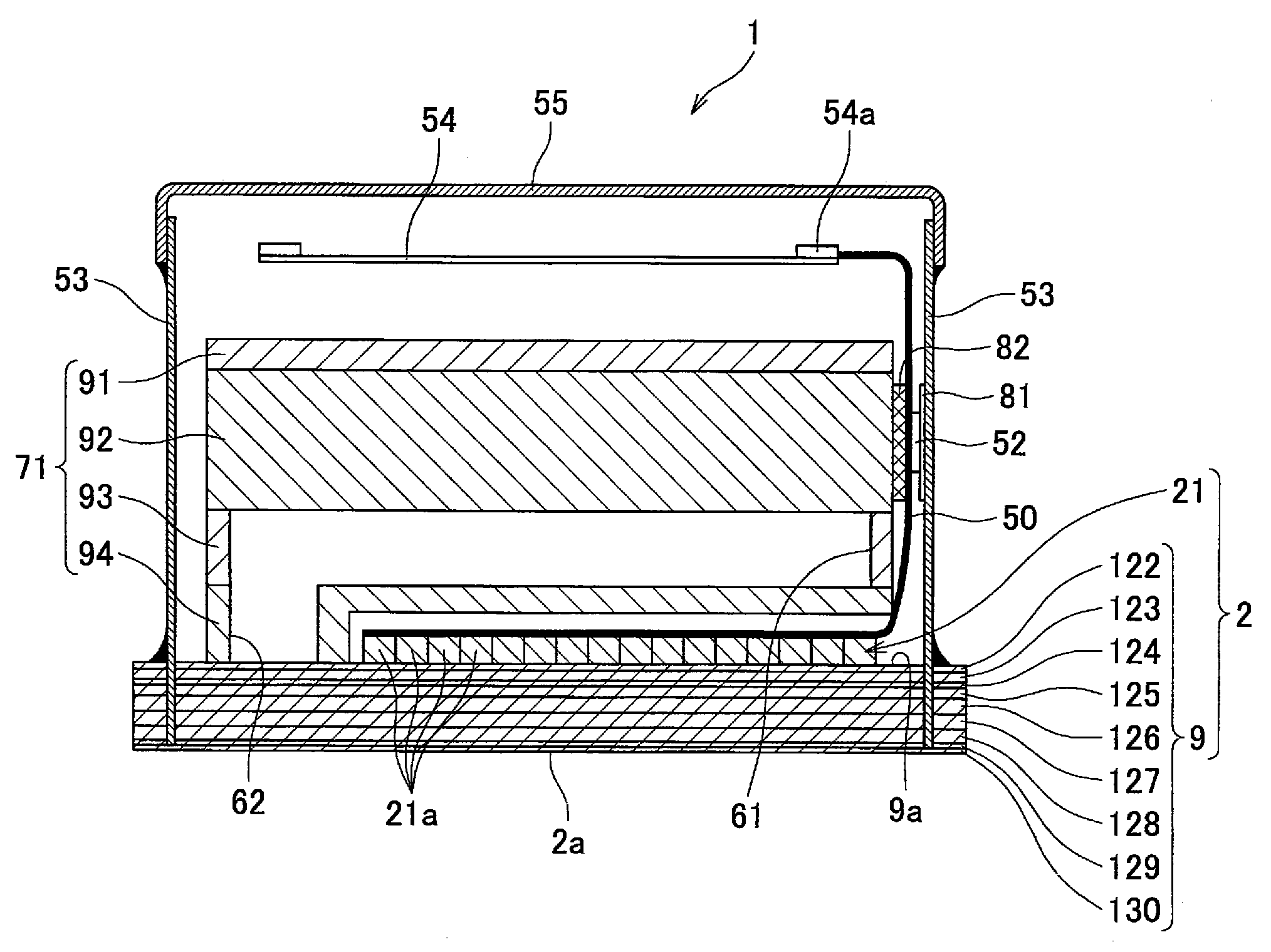
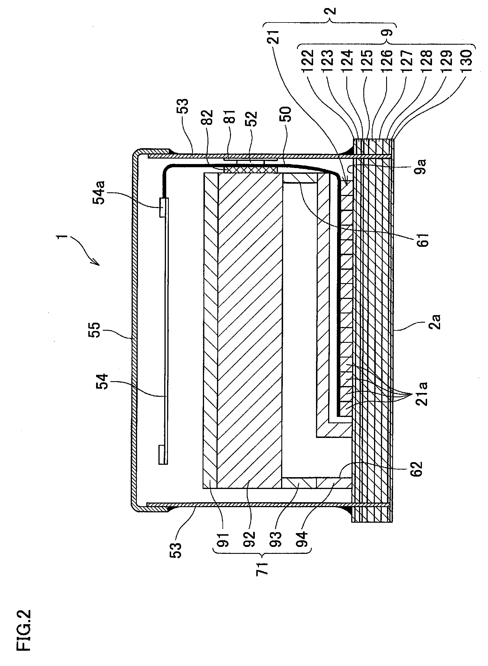
[0029]In the following, a certain preferred embodiment of the present invention will be described with reference to the accompanying drawings.

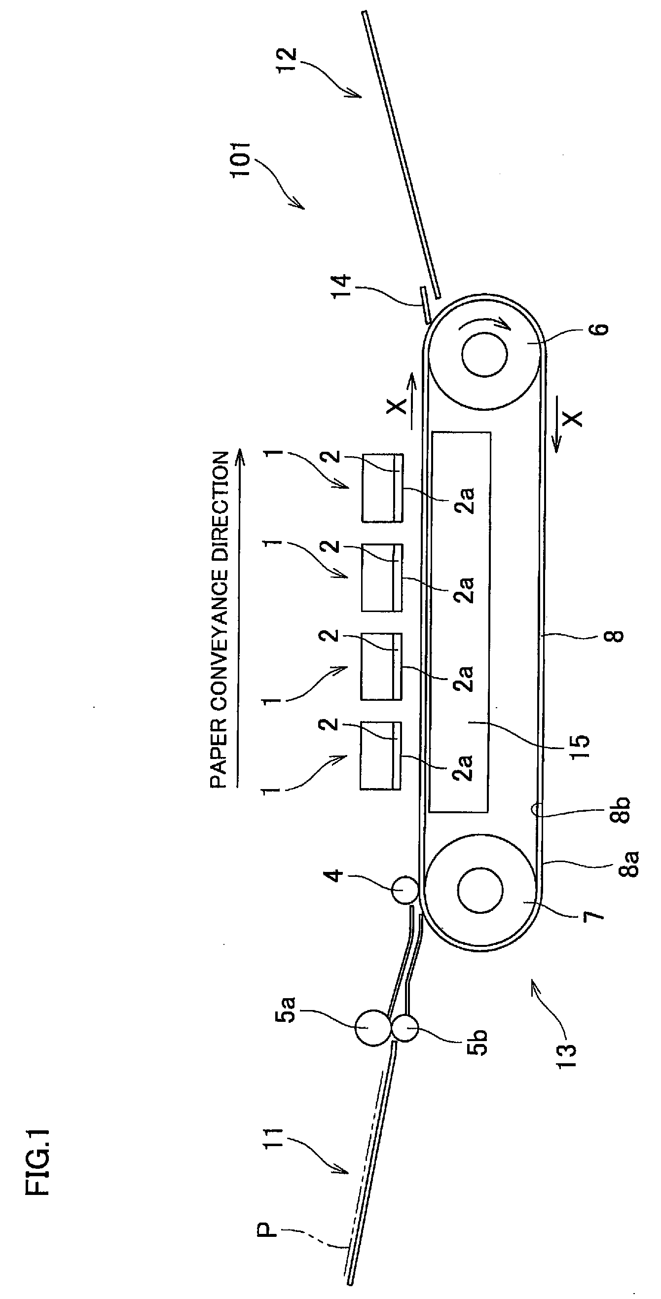
[0030]As shown in FIG. 1, an ink-jet printer 101 according to an embodiment of the present invention is a color ink-jet printer including four ink-jet heads 1. The ink-jet printer 101 has a paper feed tray 11 and a paper discharge tray 12 in left and right parts in FIG. 1, respectively. In the ink-jet printer 101, a paper conveyance path through which a paper P is conveyed from the paper feed tray 11 to the paper discharge tray 12. A pair of feed rollers 5a and 5b, which feed out the paper P from the paper feed tray 11 to a right side in FIG. 1 while pinching the paper P, are provided immediately downstream of the paper feed tray 11.

[0031]A belt conveyor mechanism 13 is provided in a middle of the paper conveyance path. The belt conveyor mechanism 13 includes two belt rollers 6 and 7, an endless conveyor belt 8 which is wound between the rolle...


PUM

PropertyMeasurementUnit
thicknessaaaaaaaaaa
thicknessaaaaaaaaaa
thicknessaaaaaaaaaa

Abstract

A liquid ejection head includes a passage member in which individual liquid passages are formed, diaphragms fixed to a plane of the passage member, piezoelectric layers formed on the diaphragms, individual electrodes formed on the respective piezoelectric layers, lands electrically connected to the respective individual electrodes. The lands have their height from a surface of the piezoelectric layers higher than that of the individual electrodes. Each of the individual liquid passages has a liquid ejection opening and a pressure chamber an interior space of which exposes on the plane. An overhang is formed on a side wall of each pressure chamber in such a manner that a length of an interior space of the pressure chamber along the plane increases at a portion more distant from the plane. At least a part of the land overlaps the overhang when seen in a direction perpendicular to the plane.

Description

CROSS REFERENCE TO RELATED APPLICATION[0001]The present application claims priority from Japanese Patent Application No. 2007-086712 which was filed on Mar. 29, 2007, the disclosure of which is herein incorporated by reference in its entirety.BACKGROUND OF THE INVENTION[0002]1. Field of the Invention[0003]The present invention relates to a liquid ejection head which ejects liquid from a liquid ejection opening, and to a method of manufacturing the liquid ejection head.[0004]2. Description of Related Art[0005]In order that an ink-jet type recording apparatus which performs printing by ejecting ink droplets realizes high-resolution printing, it is necessary to increase the number of nozzles formed in a head and in addition arrange the nozzles at a high density. In a head using piezoelectric elements, pressure chambers are formed so as to correspond to the respective nozzles. The number of pressure chambers increases as the number of nozzles increases. A possible way of arranging the p...

Claims


Application Information

Patent Timeline
Patent Type & Authority Applications(United States)
IPC IPC(8): B41J2/045H01L41/18
CPCB41J2/14209B41J2/1609B41J2/1623B41J2/1626B41J2/1631B41J2/1632Y10T29/42B41J2002/14225B41J2002/14459B41J2002/14491B41J2202/11B41J2202/20B41J2002/14217
Inventor WATANABE, HIDETOSHI
Owner BROTHER KOGYO KK
Why Eureka
Try Eureka