
llumination System

a technology of llumination system and microscopy, which is applied in the field of optical systems, can solve the problems of large size, undesirable amount of waste heat, short-lived light source, etc., and achieve the effects of low heat generation, high density of wavelength options, and efficient manufactur

Inactive Publication Date: 2014-06-12
MERMELSTEIN MICHAEL +1
View PDF0 Cites 12 Cited by
  • Summary
  • Abstract
  • Description
  • Claims
  • Application Information

AI Technical Summary

Benefits of technology

The present invention provides a microscopy system with a high density of wavelength options, low heat generation, and low cost. By using a circuit board with mechanical and electrical properties, the system has a selectable illumination wavelength and conditioning optics. The arrangement of surface mounted light sources allows for fast switching and multi-source illumination. The high density of light sources provides options for multiple redundant wavelengths, close spatial groupings of application-specific wavelengths, and multiple source types.

Problems solved by technology

These systems are typically characterized by a large size, an undesirable amount of waste heat, and expensive, short-lived light sources.
These systems have been limited to relatively few sources by the complexity and cost of each additional dichroic element.

Method used


Image

  • llumination System
  • llumination System
  • llumination System

Examples


Embodiment Construction

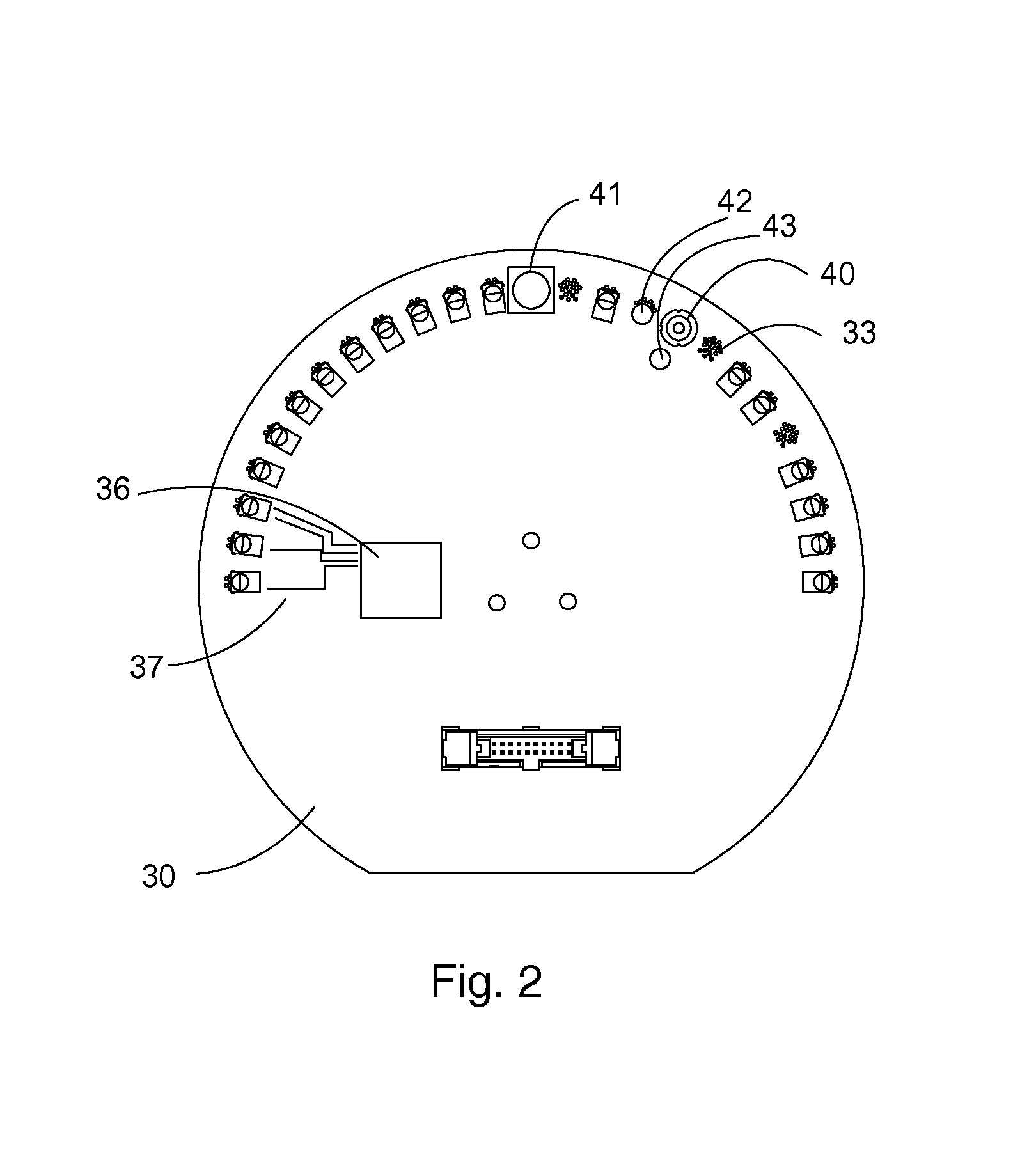
[0025]The preferred embodiment of the present invention is an illumination system for a microscope. It generally comprises a light source assembly constructed from a circuit board with a geometry and pattern of light emitting components convenient for rotational positioning and alignment with multiple optical axes. An additional embodiment includes a selectable sensor array comprising surface mounted sensors with varying sensitivities to radiation. An arrangement combining the sourcing and the sensing of light provides another embodiment.

Light Source Assembly

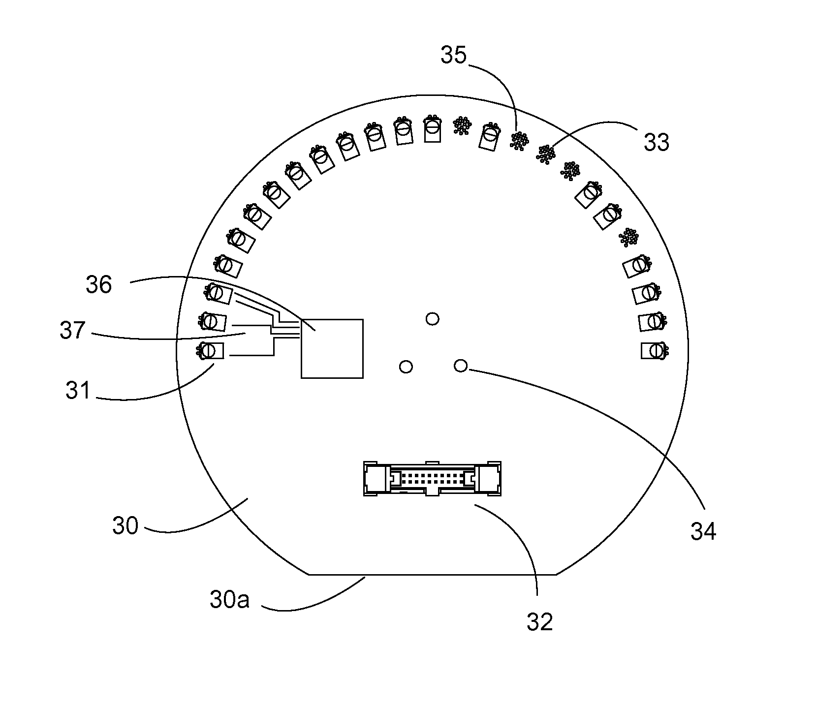
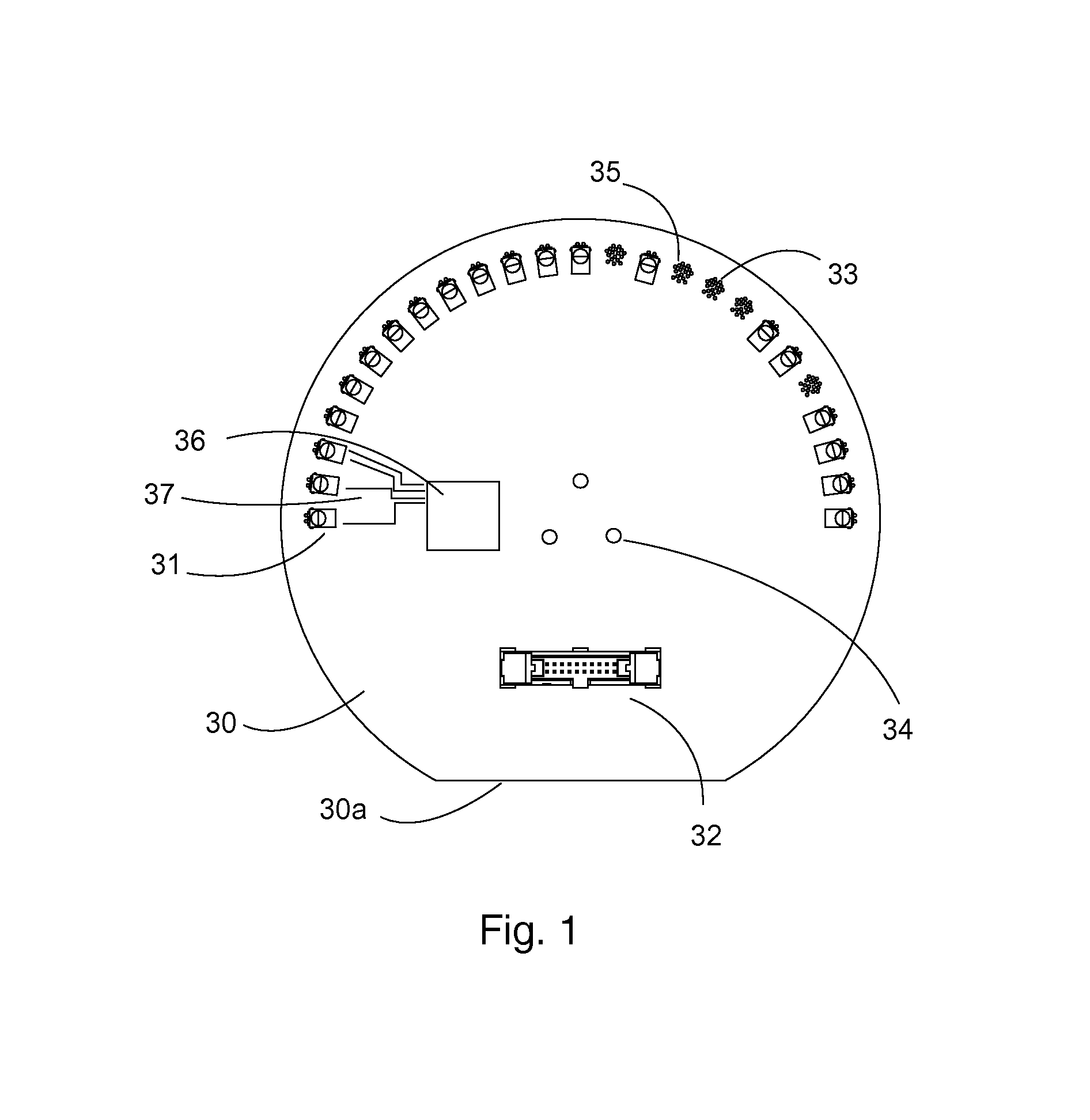
[0026]FIG. 1 shows a manufactured circuit board 30 providing multiple mounting locations 33 (i.e. 25 locations in FIG. 1). Each mounting location can be populated with an individual light emitting component 31. In this embodiment, each location is occupied by a light emitting diode (LED). Each LED is a surface mounted device soldered in place to locations or pads provided during manufacture of the circuit board. These pads are w...


PUM


Abstract

The invention is a system and method for controllable alignment of any of a plurality of electro-optical components mounted to a circuit board with an optical axis. In one embodiment, the invention provides an improved illumination system for microscopy. The system incorporates a circuit board 31 providing structure and directly mounting a plurality of light emitting sources. The mounted light sources are rotatably alignable with a plurality of optical axes. The system further includes selectable conditioning of the sources.

Description

CROSS-REFERENCE TO RELATED APPLICATIONS[0001]This application claims the benefit of provisional patent application Ser. No. 61 / 797,413, filed Dec. 6, 2012.FEDERALLY SPONSORED RESEARCH[0002]Not applicableSEQUENCE LISTING OR PROGRAM[0003]Not applicableFIELD OF THE INVENTION[0004]This invention relates to electro-optical systems and particularly to illumination systems for microscopy using a plurality of selectable sources.BACKGROUND OF THE INVENTION[0005]Fluorescence microscopy is a fundamental tool in cellular biology. It is used by researchers to monitor cellular function, to investigate gene expression, and to evaluate new drug candidates among an ever-growing collection of applications. In general, fluorescence microscopy uses a bright light source with a predetermined wavelength to excite a fluorophore (chemical label) which then emits light at a wavelength different from the excitation. Typically, as part of an illumination system, excitation colors are conditioned or otherwise ...

Claims


Application Information

Patent Timeline
Patent Type & Authority Applications(United States)
IPC IPC(8): G02B21/06
CPCG02B21/06G02B21/16G02B21/365G01N35/0099
Inventor MERMELSTEIN, MICHAELABNET, CHARLES CAMERON
Owner MERMELSTEIN MICHAEL
Learn More