Filter system for an electronic equipment enclosure

a filter system and electronic equipment technology, applied in the field of filter systems, can solve the problems of destroying electronic equipment that has not been destroyed, degrading performance, and harsh indoor environment, and achieve the effects of less expensive, less expensive, and easy cleaning

Inactive Publication Date: 2005-05-26
MARCONI INTPROP RINGFENCE +1
View PDF36 Cites 73 Cited by
  • Summary
  • Abstract
  • Description
  • Claims
  • Application Information

AI Technical Summary

Benefits of technology

[0014] There are a number of advantages, features, and objects achieved with the present invention which are believed not to be available in earlier related devices. One such advantage is that using a two filter system with a particulate filter element upstream and a water vapor filter element downstream blocks undesirable contaminants from entering the electronic enclosure and degrading the equipment inside. The two filter system also protects the water vapor filter element which is more expensive and harder to clean with the upstream particulate filter element which is less expensive and easier to clean. The invention also allows the use of commercial grade components in an outdoor electronic equipment enclosure without requiring the added cost inherent in hardening those components for a harsh climatic deployment.

Problems solved by technology

Often this class of equipment is referred to as “outside plant equipment” and / or “remote terminals.” Also, it is well known that this equipment generates heat and undesirable gas so that some sort of cooling and / or ventilation is required.
For example, humidity, salt, fog, oil, dust, rain and the like tend to degrade the performance of and potentially destroy electronic equipment that has not been properly “hardened” to allow deployment in harsh environments.
Even some indoor environments are considered harsh.
Corrosion ensues and may be increased when contaminated with industrial pollutants, such as chlorides and sulfides.

Method used


Image

  • Filter system for an electronic equipment enclosure
  • Filter system for an electronic equipment enclosure
  • Filter system for an electronic equipment enclosure

Examples


Embodiment Construction

[0020] While the present invention is open to various modifications and alternative constructions, the preferred embodiment shown in the various figures of the drawing will be described herein in detail. It is understood, however, that there is no intention to limit the invention to the particular embodiment, form or example disclosed. On the contrary, the intention is to cover all modifications, equivalent structures and methods, and alternative constructions falling within the spirit and scope of the invention as expressed in the appended claims, pursuant to Title 35 U.S.C. section 112 (second paragraph).

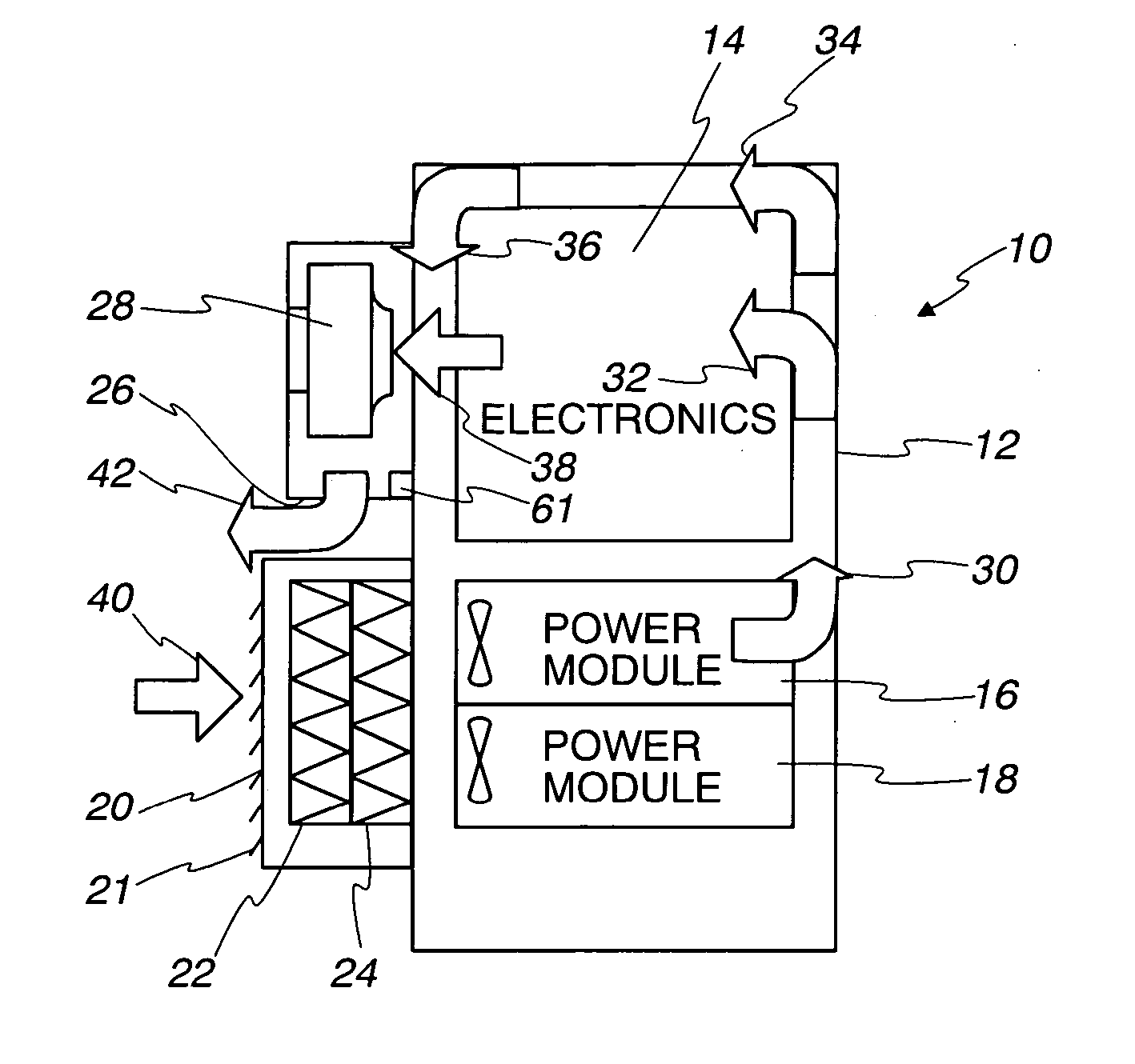
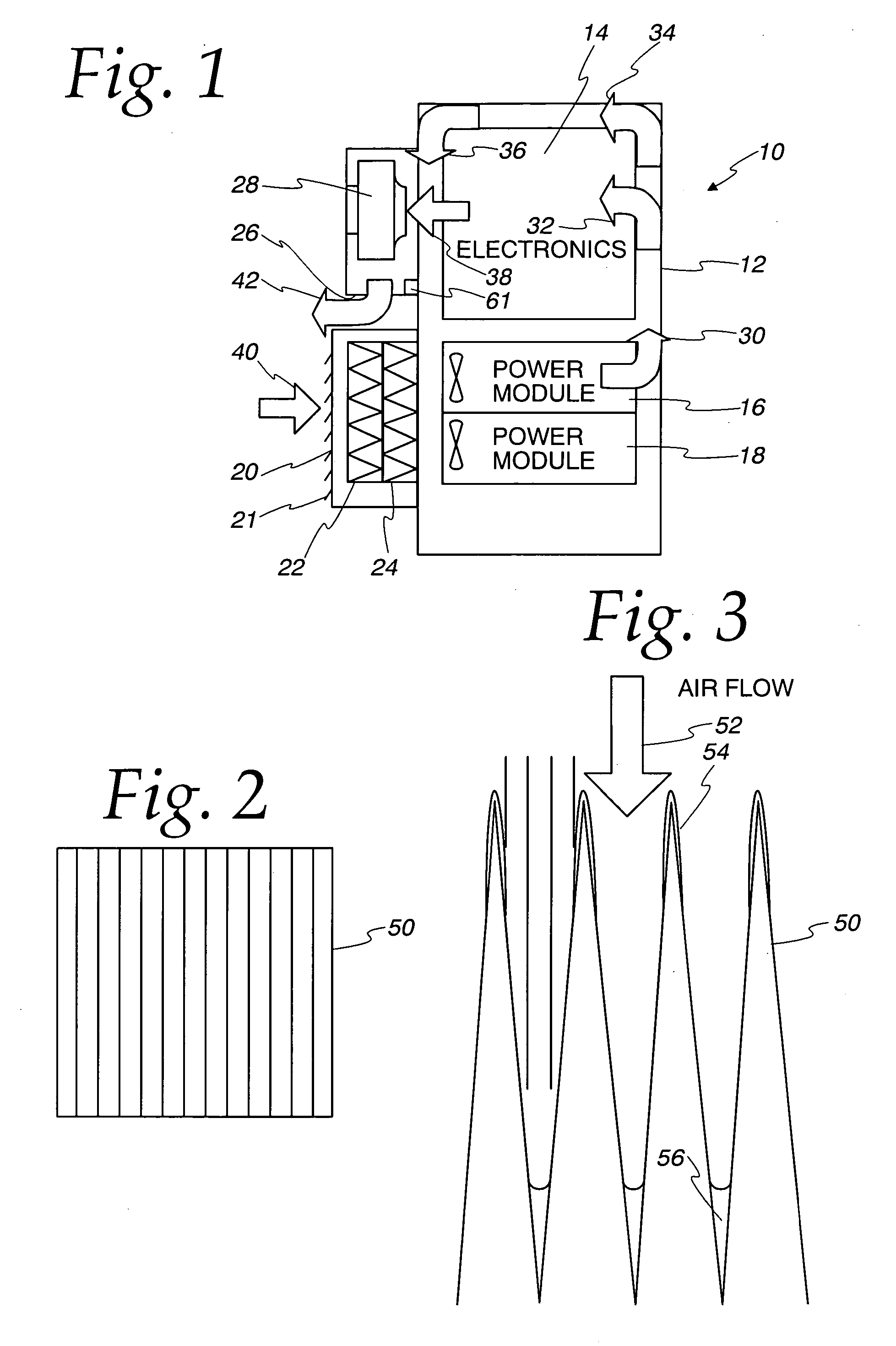
[0021] Referring now to FIG. 1, there is shown a diagrammatical outdoor enclosure 10 having a main housing 12 which has in its upper portion sensitive electronic equipment 14 and in its lower portion two power modules 16, 18. In keeping with the present invention, an inlet housing 20 is provided to allow ingress of ambient air through a louver 21 and two filter elements, an ASHRA...


PUM

PropertyMeasurementUnit
diameteraaaaaaaaaa
diametersaaaaaaaaaa
diametersaaaaaaaaaa

Abstract

A filter system including a method for self cleaning the filter system of an electronic equipment enclosure where air flow is monitored either by monitoring fan performance or air flow velocity through the enclosure. The system includes two filters elements, an upstream ASHRAE or HEPA filter element to block particulate matter and a downstream PTFE filter element to block water vapor. The ASHRAE or HEPA filter element is relatively inexpensive and easy to clean. The PTFE filter element is more expensive and difficult to clean. Thus, the cheaper filter is used to protect the more expensive filter from contaminants and to increase its useful life. The method of self cleaning includes stopping the fan when a signal is received indicating a predetermined resistance to air flow which is a function of blockage of the filter elements, thereafter operating the fan at an increased rotational velocity to determine whether the fan itself is malfunctioning, thereafter slowing and stopping the fan to allow the fan to be reversed, rotating the fan in reverse for a predetermined period of time, such as five minutes, thereafter slowing and stopping the fan and returning the fan to its usual rotational velocity and direction. If the resistance to air flow is still above a predetermined level, the fan is again slowed, stopped and reversed and then returned to normal operation. The reversal operation can be conducted a multiple number of times, however, after a predetermined number, a signal is sent requesting maintenance.

Description

CROSS REFERENCE TO RELATED APPLICATION [0001] Not applicable. STATEMENT RE FEDERALLY SPONSORED RESEARCH [0002] Not applicable. BACKGROUND OF THE INVENTION [0003] 1. Field of the Invention [0004] The present invention relates to a filter system, and more particularly to a two filter element system for filtering particulate matter from an air flow path at an upstream location and water vapor at a downstream location. [0005] 2. Description of the Related Art [0006] Electronic equipment enclosures are often located out-of-doors. Examples of such electronic hardware are telecommunication equipment, cable television equipment and data transmission equipment. Often this class of equipment is referred to as “outside plant equipment” and / or “remote terminals.” Also, it is well known that this equipment generates heat and undesirable gas so that some sort of cooling and / or ventilation is required. Further, this outside plant equipment may be located just about any place on earth, where it may...

Claims


Application Information

Patent Timeline
Patent Type & Authority Applications(United States)
IPC IPC(8): B01D46/00B01D46/12B01D46/46B01D46/54G11B33/14H05K7/20
CPCB01D46/0023B01D46/0086B01D46/12B01D46/46H05K7/20181B01D2267/40B01D2273/30G11B33/146B01D46/54Y10S95/90B01D46/62
Inventor LATHAM, STEVEN R.GARCIA, MARVIN P.COSLEY, MICHAEL R.
Owner MARCONI INTPROP RINGFENCE
Why Eureka
Try Eureka