
Air purification system and method

a technology of air purification system and air filter, which is applied in the direction of heating types, lighting and heating apparatus, separation processes, etc., can solve the problems of pollution in rural areas, health and life style problems, and pollution in rural areas along coastlines

Inactive Publication Date: 2005-05-26
LEE DAVID B
View PDF25 Cites 29 Cited by
  • Summary
  • Abstract
  • Description
  • Claims
  • Application Information

AI Technical Summary

Benefits of technology

"The present invention is an air purification system and method that provides clean, cool, and dry air for use in buildings. The system removes pollutants from incoming polluted air, pre-cools it to provide a clean, cool, moist airflow, and then condenses water out of it to provide a substantially clean, dry airflow. The technical effects of the invention include providing substantially pollutant-free dry air for use in a building, providing cool, clean air for facilities that require dehydrated and purified cool air, and meeting specific air quality requirements. The invention is affordable, reliable, and effective in achieving its intended purposes."

Problems solved by technology

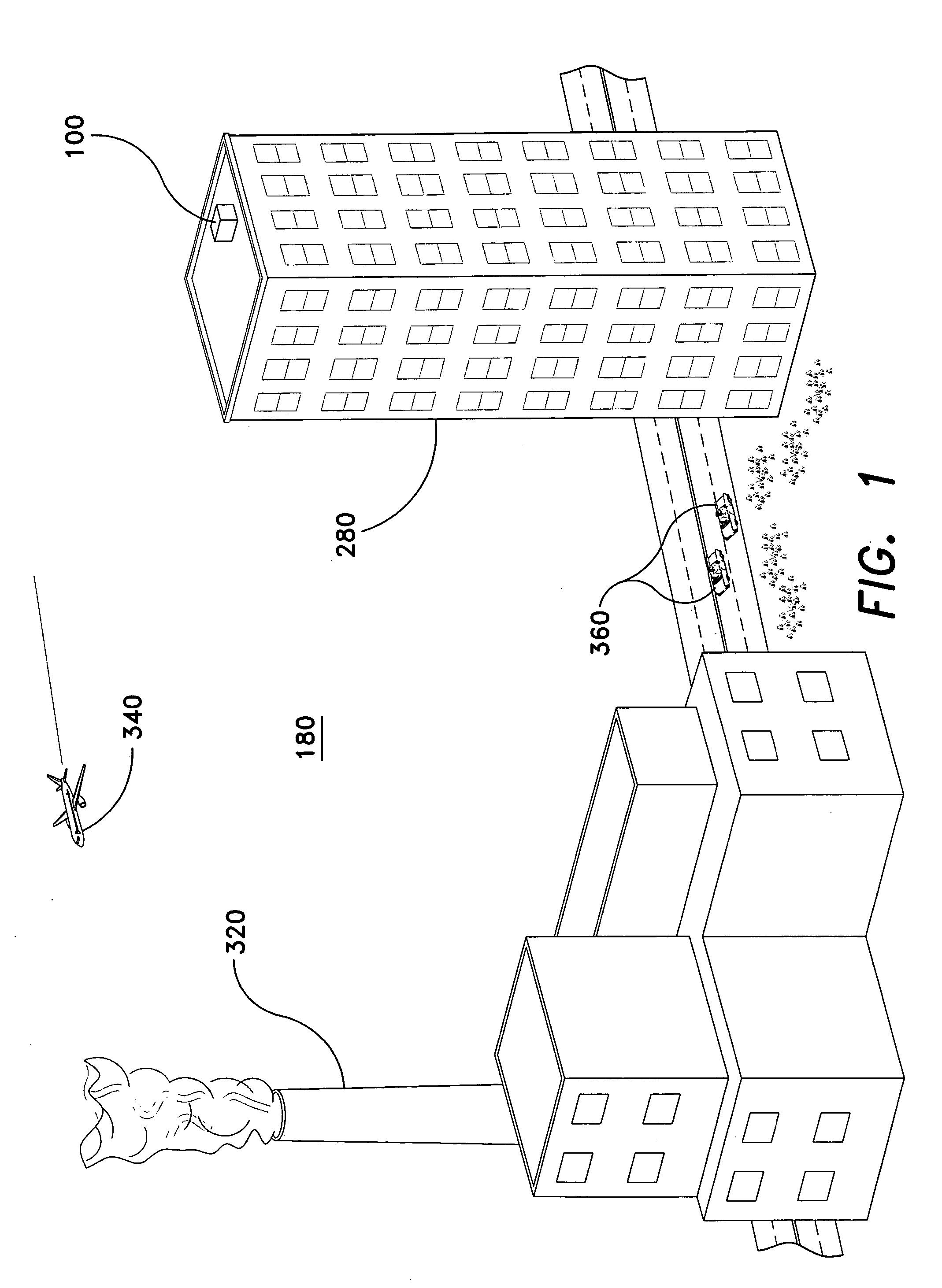
Air quality has become a serious health and life-style issue.
Rural areas can also suffer from pollution.
For example, rural areas along coastlines may be subjected to pollution from oil refineries and other coastal facilities devoted to processing or manufacturing chemicals.
Thus, air pollution can be a serious problem in urban and rural areas.
The '302 device has numerous problems in use.
The '302 device explicitly adds humidity to the cleaned air and, absent a humidity removal stage, the '302 device is not suitable for use in a humid location.
The efficiency of the '148 device is dramatically impacted if the charging device is not maintained in a clean condition.
U.S. Pat. No. 6,059,866, issued to Yamagata et al., shows a device in FIG. 21 that appears to be identical to FIG. 1 of the Japanese '122 patent, and notes that the device does not provide for humidifying the air.

Method used


Image

  • Air purification system and method
  • Air purification system and method
  • Air purification system and method

Examples


Embodiment Construction

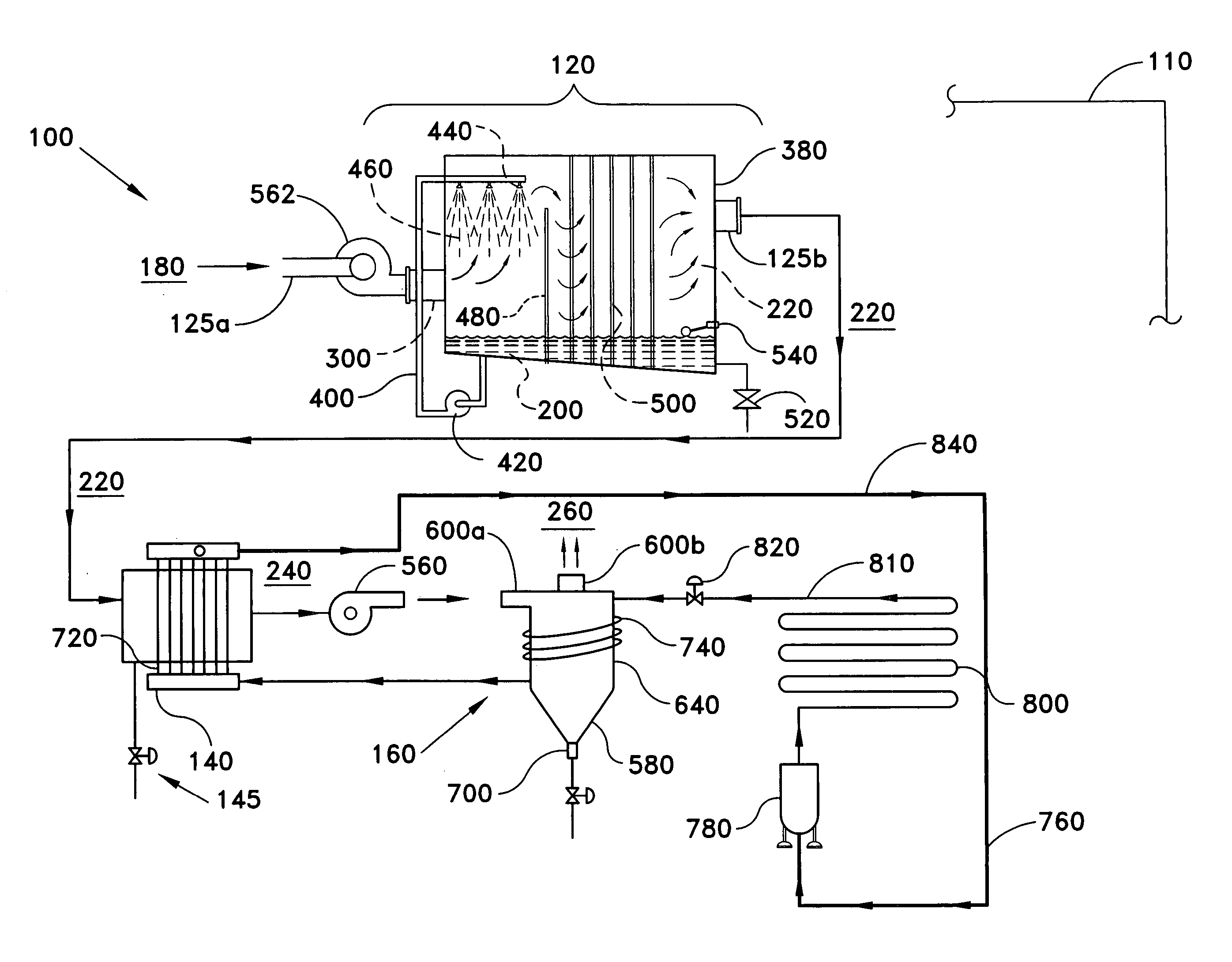
[0028] The present invention is directed to an air purification system and method. More specifically, the invention is directed to an air purification system that has an air pollutant removal stage, an air pre-cooling unit, and a dual cooling and water removal unit.

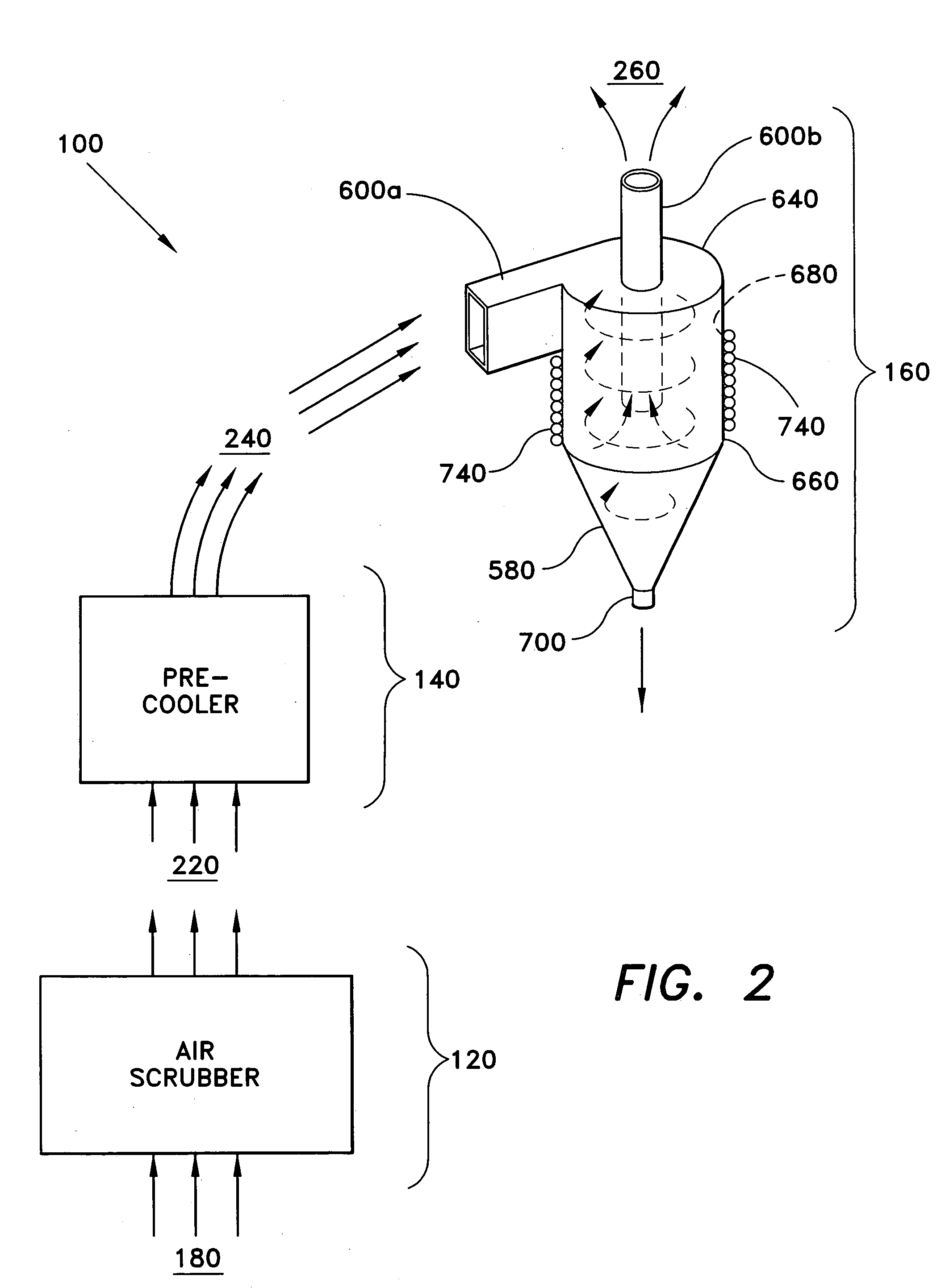
[0029]FIG. 2 is a schematic diagram showing how polluted air 180 is processed by the air purification system 100 according to the invention. Polluted air 180 is drawn and / or blown into an air pollutant removal stage 120 including an air scrubber where water is used to clean the air 180 to provide a substantially pollutant free outgoing moist airflow 220. The airflow 220 is directed to a pre-cooling stage 140 including a pre-cooler that cools the air 220 to provide a clean cool moist airflow 240. The airflow 240 is then directed to a dual cooling and water removal stage 160, which condenses water out of the airflow 240 to provide a substantially dehydrated and purified cold airflow 260 suitable for use in a building. Duct...


PUM

PropertyMeasurementUnit
pressureaaaaaaaaaa
temperatureaaaaaaaaaa
humidityaaaaaaaaaa

Abstract

The air purification system and method for purifying and cooling air for use in a building has an air pollutant removal stage, an air pre-cooling unit, and a dual cooling and water removal unit, including a cyclone separator having a cooling coil wrapped around the separator for condensing and removing water from the airflow. The method comprises the steps of removing pollutants from an incoming polluted airflow to provide a substantially pollutant free outgoing moist airflow; pre-cooling the substantially pollutant free moist airflow to provide a clean cool moist airflow; and condensing water out of the clean cool moist airflow to provide a substantially clean dry airflow suitable for use in a building.

Description

CROSS-REFERENCE TO RELATED APPLICATION [0001] This application claims the benefit of U.S. Provisional Patent Application Ser. No. 60 / 524,851, filed Nov. 26, 2003.BACKGROUND OF THE INVENTION [0002] 1. Field of the Invention [0003] The present invention relates to an air purification system and method. More specifically, the invention is directed to an air conditioning system and method that has an air pollutant removal stage, a pre-cooling stage, and a dual cooling and water removal stage. [0004] 2. Description of the Related Art [0005] Air quality has become a serious health and life-style issue. There is a plethora of sources of pollution including, but not limited to: large trucks with diesel engines (source for, e.g., particulate matter, hydrocarbons, and carbon monoxide), gasoline driven vehicles (carbon monoxide, sulfur oxides (SOX), hydrocarbons), aircraft engines (carbon monoxide, and hydrocarbons such as benzene), and coal fired power stations (SOX and particulates). Rural a...

Claims


Application Information

Patent Timeline
Patent Type & Authority Applications(United States)
IPC IPC(8): B01D45/12B01D53/14B01D53/26F24F3/14F24F8/133F24F8/28
CPCB01D45/12B01D53/14B01D53/265F24F2006/146F24F3/16F24F2003/1617F24F3/1405Y02A50/20F24F8/117F24F8/28F24F8/133
Inventor LEE, DAVID B.
Owner LEE DAVID B
Learn More