Cleaning system and method of use

a cleaning system and cleaning method technology, applied in the field of cleaning apparatus, can solve the problems of high cost, time-consuming and labor-intensive, and the use of high-pressure hoses to clean the tanks, and achieve the effects of simple design, reduced cost, and enhanced usefulness of cleaning apparatus

Inactive Publication Date: 2005-05-26
NUSYST INC
View PDF3 Cites 38 Cited by
  • Summary
  • Abstract
  • Description
  • Claims
  • Application Information

AI Technical Summary

Benefits of technology

[0008] Another aspect of the invention provides a cleaning apparatus having a pair of spray heads operable to spray liquid independently from one another. The apparatus has a frame for carrying a motor and a pump, with the pump having an inlet and an outlet and being in operable communication with the motor. A pair of hose lines is arranged in fluid communication with the outlet of the pump. Each hose line has a valve to control the flow of fluid therethrough so that the hose lines can operate independently from one another. Each spray head is attached to a separate hose line, thereby enabling the spray heads to spray fluid independently from one another.
[0009] Some of the potential objects, features and advantages included in at least some of the presently preferred embodiments of this invention, by way of example and without limitations, include an improved cleaning apparatus that is able to clean more than one surface at a time, provides mobility of the cleaning apparatus, enhances the usefulness of the cleaning apparatus, is capable of spraying different solutions at the same time, reduces the costs associated with cleaning surfaces of a tank, is of relatively simple design, is economical in manufacture and assembly, and reduces the harmful risks involved with cleaning the interior surfaces of enclosed chemical vessels.

Problems solved by technology

This is particularly troublesome with solutions prone to build-up on surfaces in the form of solids, sludges, and slimes, such as occurs with latex, silicone, enamel, and the like.
Utilizing high pressure hoses to clean the tanks is not only time consuming, and thus, costly, but it can prove hazardous if the person comes in contact with the high pressure jet stream.
In addition, the person within the tank must often take proper precautions to avoid exposure to potentially hazardous chemicals and dangers of working in a confined space.

Method used


Image

  • Cleaning system and method of use
  • Cleaning system and method of use
  • Cleaning system and method of use

Examples


Embodiment Construction

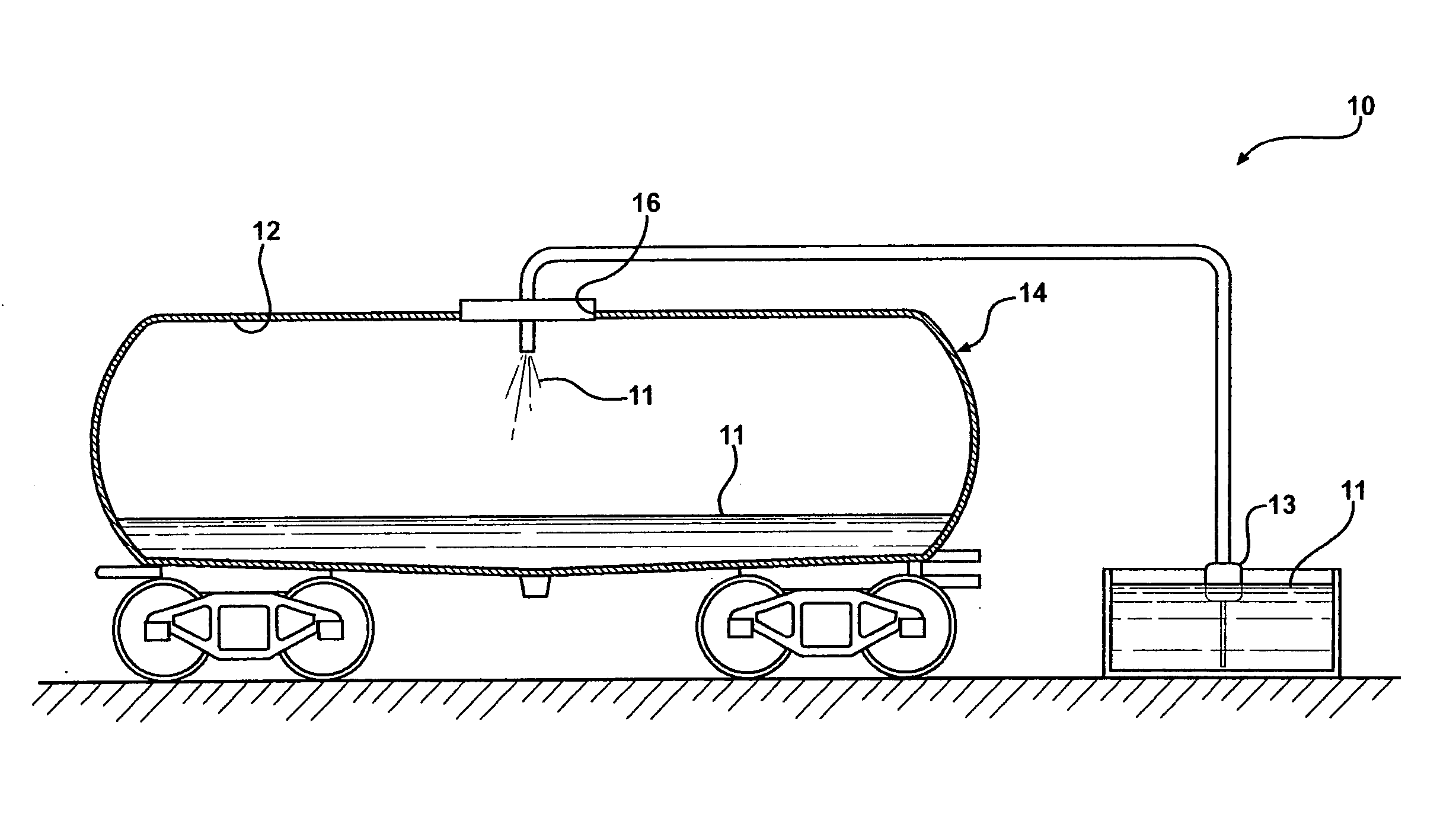
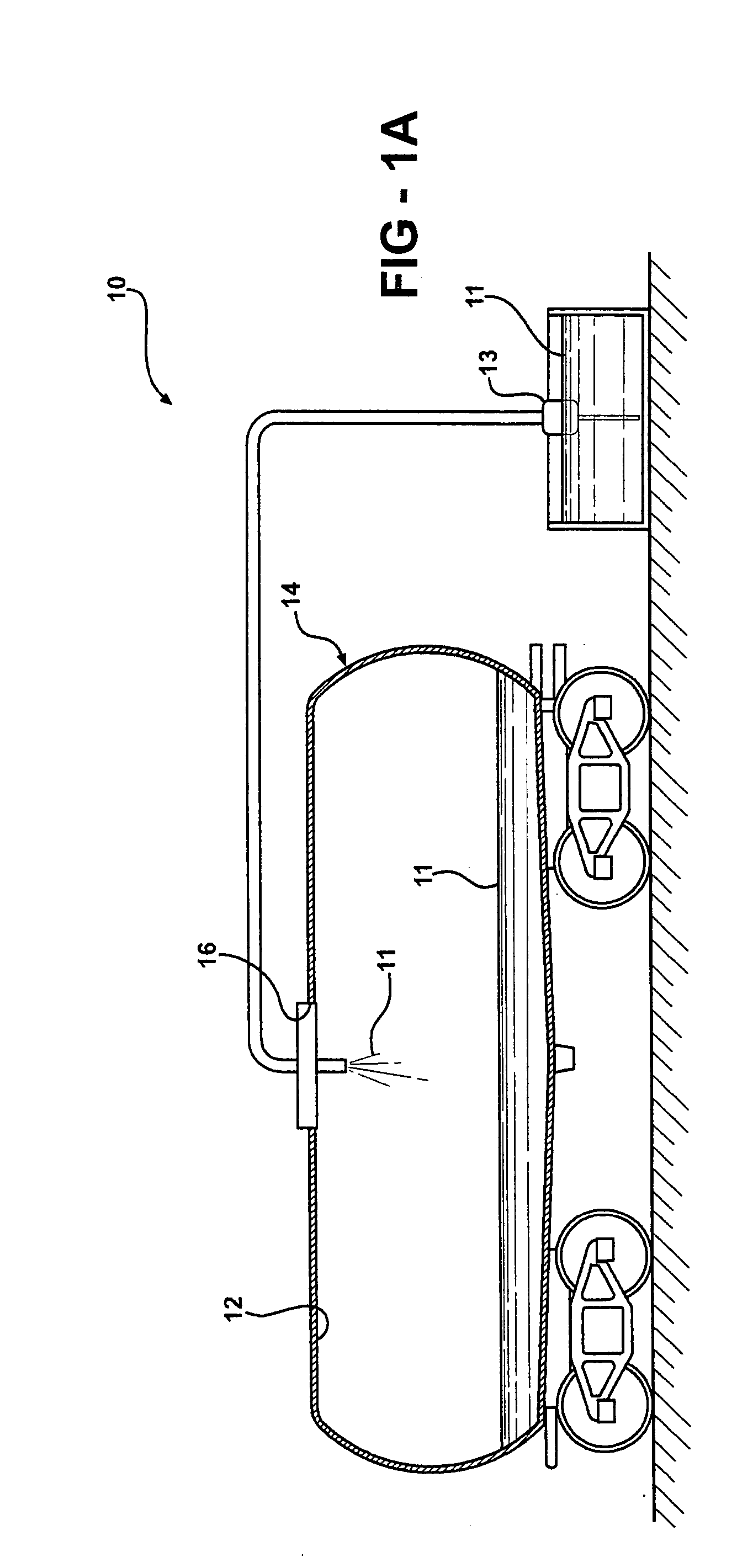
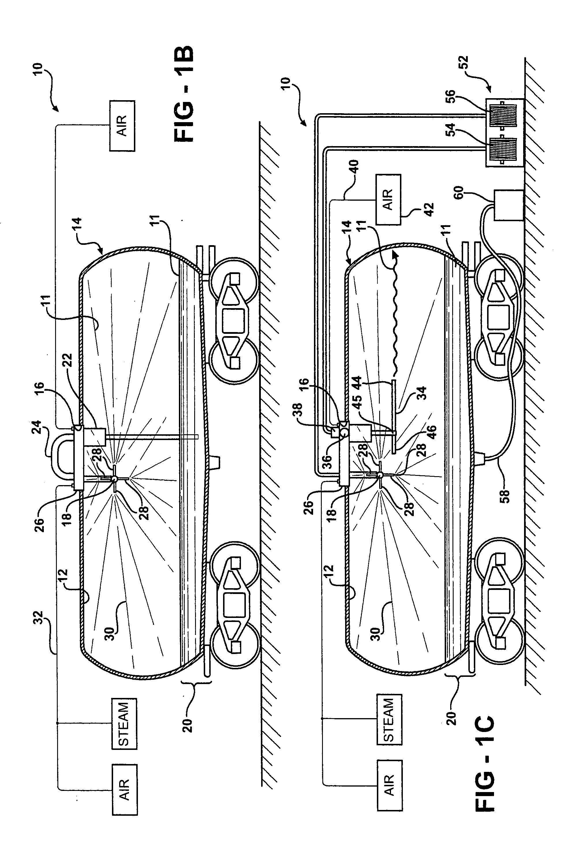
[0018] Referring in more detail to the drawings, FIGS. 1A-1E illustrate a cleaning system 10 according to one aspect of the invention. The cleaning system 10 is generally suitable for cleaning interior and / or exterior surfaces as desired, and is shown here, by way of example and without limitations, being used to clean an inner surface 12 of a rail car 14. It should be recognized that the cleaning system 10 can be used to clean an inner and / or outer surface of any tank, vessel, pipe, or the like. The cleaning system 10 allows the rail car 14 to be cleaned in the absence of a person being present in the tank, thereby eliminating potential sources of hazard to a person, such as being exposed to an extremely high pressure jet stream of liquid, i.e. 20,000-40,000 psi, or being exposed to toxic chemicals. In addition, the cleaning system 10 greatly reduces the amount of water consumed during the cleaning process, thus, reducing the associated costs for cleaning the rail car 14.

[0019] In...


PUM


Abstract

A method, system and apparatus for cleaning a tank through the use of a pair of spray heads arranged in operable communication with a pump via a pair of hose lines. One of the spray heads is operable to disperse a heated mist of cleaning solution, while the other spray head is operable to dispense a jet stream of the cleaning solution. The spray heads can be arranged in a closed loop, recirculating flow of the cleaning solution between the pump and the spray heads, or an open loop. Each hose line has a valve to control the flow of the cleaning solution therethrough so that the spray heads can operate independently from one another.

Description

REFERENCE TO CO-PENDING APPLICATION [0001] This application claims the benefit of U.S. Provisional Application No. 60 / 523,554, filed Nov. 20, 2003.BACKGROUND OF THE INVENTION [0002] 1. Field of the Invention [0003] This invention relates generally to cleaning apparatus, and more particularly to cleaning apparatus and their method of use for dispensing fluid under pressure onto a surface or surfaces being cleaned. [0004] 2. Related Art [0005] Generally, large tanks, such as rail car tanks for example, or other vessels used in transporting liquids, accumulate a build-up of material on interior tank surfaces over time. This is particularly troublesome with solutions prone to build-up on surfaces in the form of solids, sludges, and slimes, such as occurs with latex, silicone, enamel, and the like. To avoid contamination, when the particular liquid is emptied from the tank, it is necessary to clean the tank prior to reusing the tank. Cleaning the tank typically involves one or more perso...

Claims


Application Information

Patent Timeline
Patent Type & Authority Applications(United States)
IPC IPC(8): B08BB08B3/12B08B9/00B08B9/093
CPCB08B9/0936B08B9/093
Inventor GREGORY, DAVID B.
Owner NUSYST INC
Why Eureka
Try Eureka