Electric park brake mechanism and method of operating an electric brake to perform a park brake function

a technology of electric brake and parking brake, which is applied in the direction of braking system, friction lining, transportation and packaging, etc., can solve the problems of uncontrolled braking, the problem of reducing the service life of the brake actuator, and the inability to solve the brake function by simply locking the brake actuator in a fixed position

Active Publication Date: 2005-05-26
HONEYWELL INT INC
View PDF10 Cites 39 Cited by
  • Summary
  • Abstract
  • Description
  • Claims
  • Application Information

AI Technical Summary

Benefits of technology

[0009] An additional aspect of the invention comprises an electromechanical parking brake that includes a brake device for braking a vehicle, an EMA device for actuating the brake means, a bistable clamp device for selectively preventing movement of a portion of the EMA device, and a control device for controlling the clamp device.
[0010] Another aspect of the invention comprises an electromechanical braking system that includes at least one stator movable into contact with at least one rotor to brake the at least one rotor, an EMA for moving the stator, a bistable clamp for selectively preventing movement of a portion of the EMA, and a controller for controlling the clamp.

Problems solved by technology

Uncommanded braking is considered a more serious failure mode than loss of braking.
Attempting to implement a park brake function by simply locking the brake actuators in a fixed position does not solve the problem because of the effects of differential thermal expansion in the brake heat stack.

Method used


Image

  • Electric park brake mechanism and method of operating an electric brake to perform a park brake function
  • Electric park brake mechanism and method of operating an electric brake to perform a park brake function
  • Electric park brake mechanism and method of operating an electric brake to perform a park brake function

Examples


Embodiment Construction

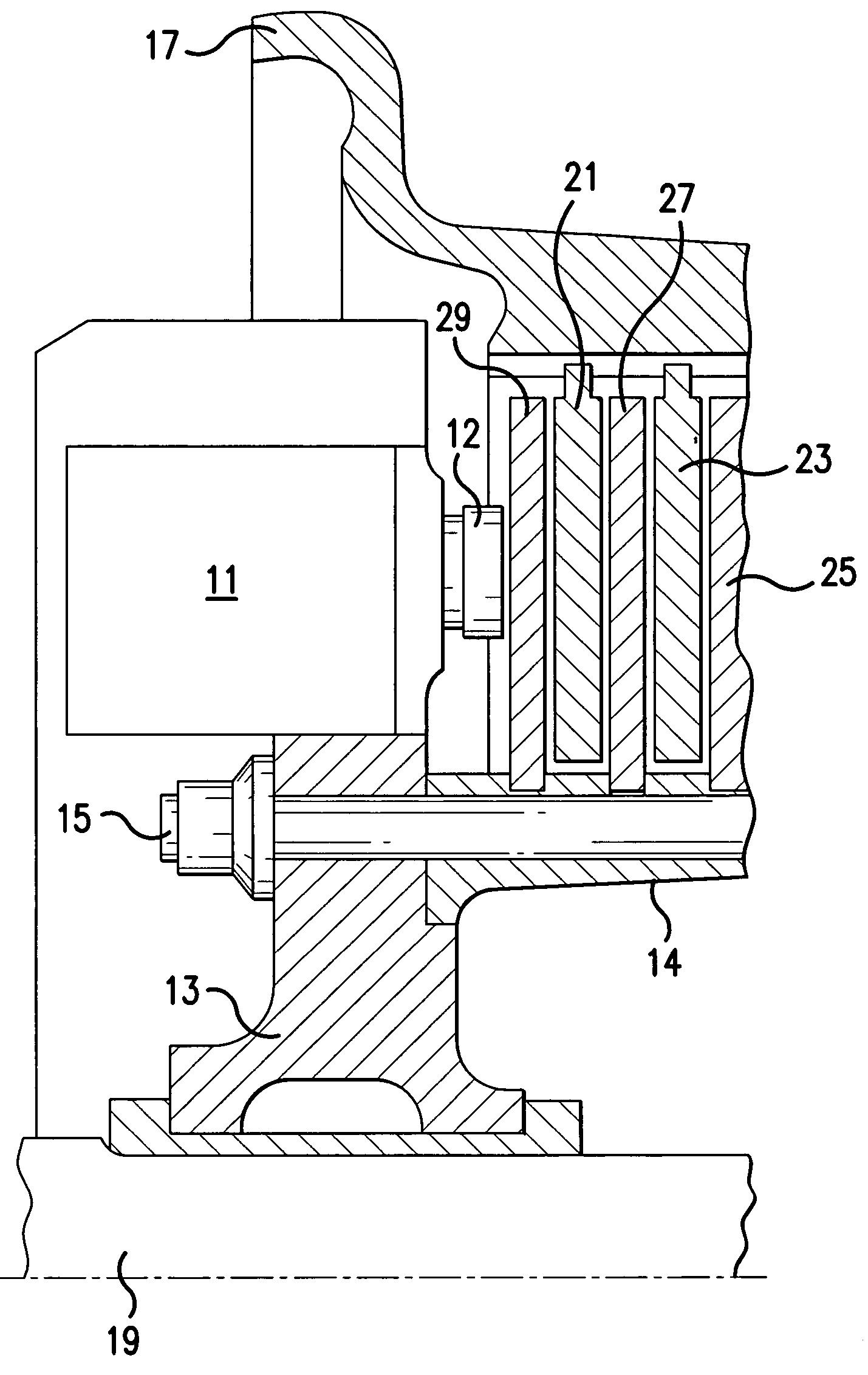
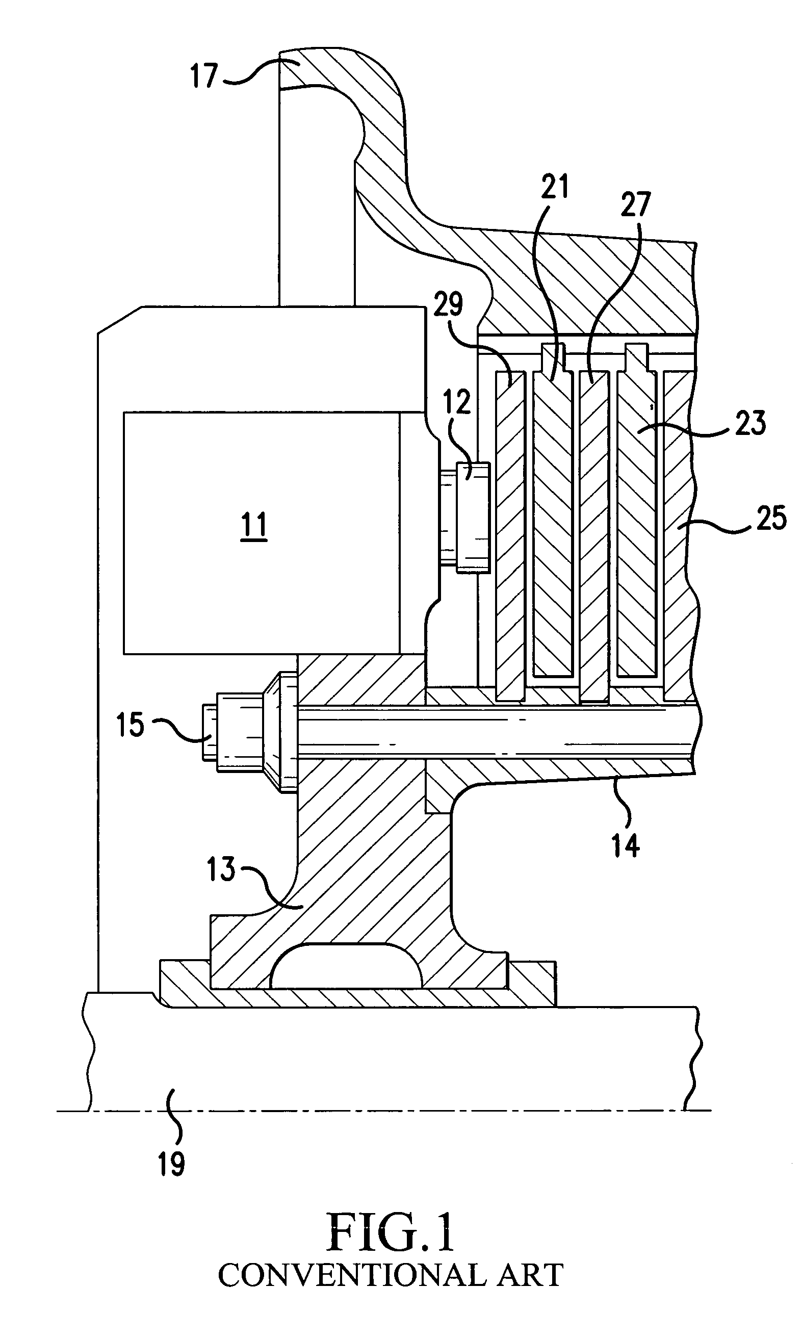
[0030] In one aspect, an embodiment of the present invention is an EMA braking arrangement having a parking brake function. According to another aspect, an embodiment of the present invention is a method for controlling an EMA braking arrangement having a parking brake function. Other aspects of embodiments of the present invention will become evident from the following description, with reference to the drawings.

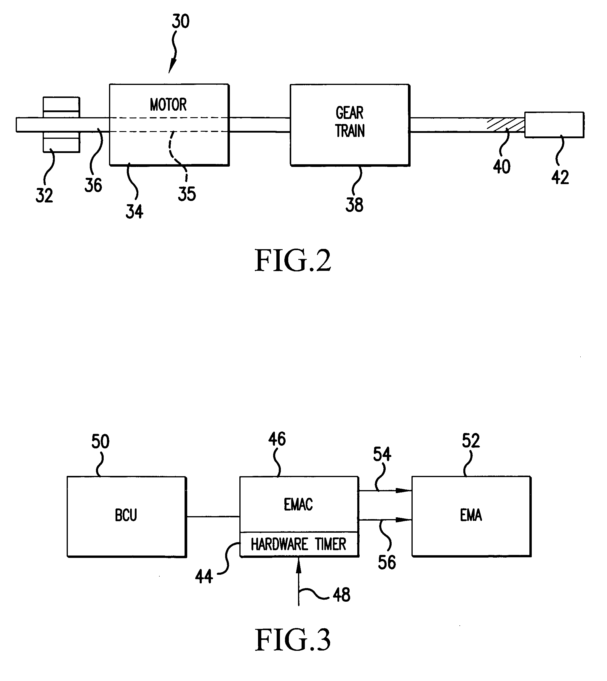
[0031] An embodiment of the present invention solves the above-described problems so as to: minimize power consumption during parking function; avoid uncommanded braking when power is lost; and avoid loss of park brake holding force due to differential thermal expansion. In one embodiment, these results are achieved by combining two technologies: (1) a mechanically or magnetically bistable securing or clamping mechanism which can be electrically commanded with a momentary pulse of power to lock (or unlock) the motor shaft of the EMA in order to “set” (or release) the park ...


PUM


Abstract

An electromechanical braking system is disclosed that includes a brake rotor, a brake stator, an EMA (52) having a rotor shaft (36), a ram (42) operably connected to the EMA (52) having a first end movable between a first position urging the brake stator against the brake rotor and a second position, a clamp device (32) shiftable between a first clamping position in clamping engagement with the rotor shaft (36) and a second clamping position and a clamp controller (46) for shifting the clamping device (32) between the first and second clamping positions. A method of using the braking system as a parking brake is also disclosed.

Description

CROSS REFERENCE TO RELATED APPLICATIONS [0001] The present application claims the benefit of U.S. Provisional Patent Application No. 60 / 524,643, filed Nov. 25, 2003, the entire contents of which are hereby incorporated by reference.FIELD OF THE INVENTION [0002] This invention relates to braking systems utilizing electromechanical actuators, and more particularly to a method and apparatus for implementing a parking brake function for an electromechanically actuated aircraft brake. BACKGROUND OF THE INVENTION [0003] Braking systems using electromechanical actuators (EMAs) have been considered as alternatives to conventional hydraulic braking arrangements. In one previously disclosed aircraft braking arrangement using EMAs, a plurality of EMAs are mounted on a brake carrier housing in an annular pattern about the axis of wheel rotation. The brake carrier housing is fixed to a torque tube having stator disks of a brake disk stack attached thereto. Rotor disks of the brake disk stack, wh...

Claims


Application Information

Patent Timeline
Patent Type & Authority Applications(United States)
IPC IPC(8): B60T7/04B60T7/10F16D65/28B60T13/74F16D65/00F16D65/14
CPCB60T7/107B60T13/741F16D2127/06F16D2121/24F16D65/18
Inventor ETHER, RUSS
Owner HONEYWELL INT INC
Why Eureka
Try Eureka