Constant discharge structure for nozzle head lowering type vacuum cosmetic container

a technology of nozzle head and structure, which is applied in the direction of packaging foodstuffs, instruments, packaged goods, etc., can solve the problems of complex structure and sensitive ingredients, and achieve the effect of safe protection of contents in containers

Inactive Publication Date: 2005-05-26
CDR
View PDF8 Cites 4 Cited by
  • Summary
  • Abstract
  • Description
  • Claims
  • Application Information

AI Technical Summary

Benefits of technology

[0008] It is, therefore, an object of the present invention to safely protect contents in a container from air and sunlight without acidification by filling the real contents in the container without having an idle air layer in the upper portion thereof after discharging the contents. Differently from a nozzle head restoring type airless cosmetics container, whenever a nozzle head is pressed, a contents pumping member is lowered by a predetermined distance, the real contents are discharged according to the lowering distance, and a contents inflow hole is closed by a valve formed in the lower end of a central shaft to prevent the nozzle head from being more lowered, thereby discharging a constant amount of contents.

Problems solved by technology

Such ingredients are sensitive.
In addition, the structure is quite complicated.

Method used


Image

  • Constant discharge structure for nozzle head lowering type vacuum cosmetic container
  • Constant discharge structure for nozzle head lowering type vacuum cosmetic container
  • Constant discharge structure for nozzle head lowering type vacuum cosmetic container

Examples


Embodiment Construction

[0021] Preferred embodiments of the present invention will now be described with reference to the accompanying drawings. In the following description, same drawing reference numerals are used for the same elements even in different drawings. The matters defined in the description such as a detailed construction and elements of a circuit are nothing but the ones provided to assist in a comprehensive understanding of the invention. Thus, it is apparent that the present invention can be carried out without those defined matters. Also, well-known functions or constructions are not described in detail since they would obscure the invention in unnecessary detail.

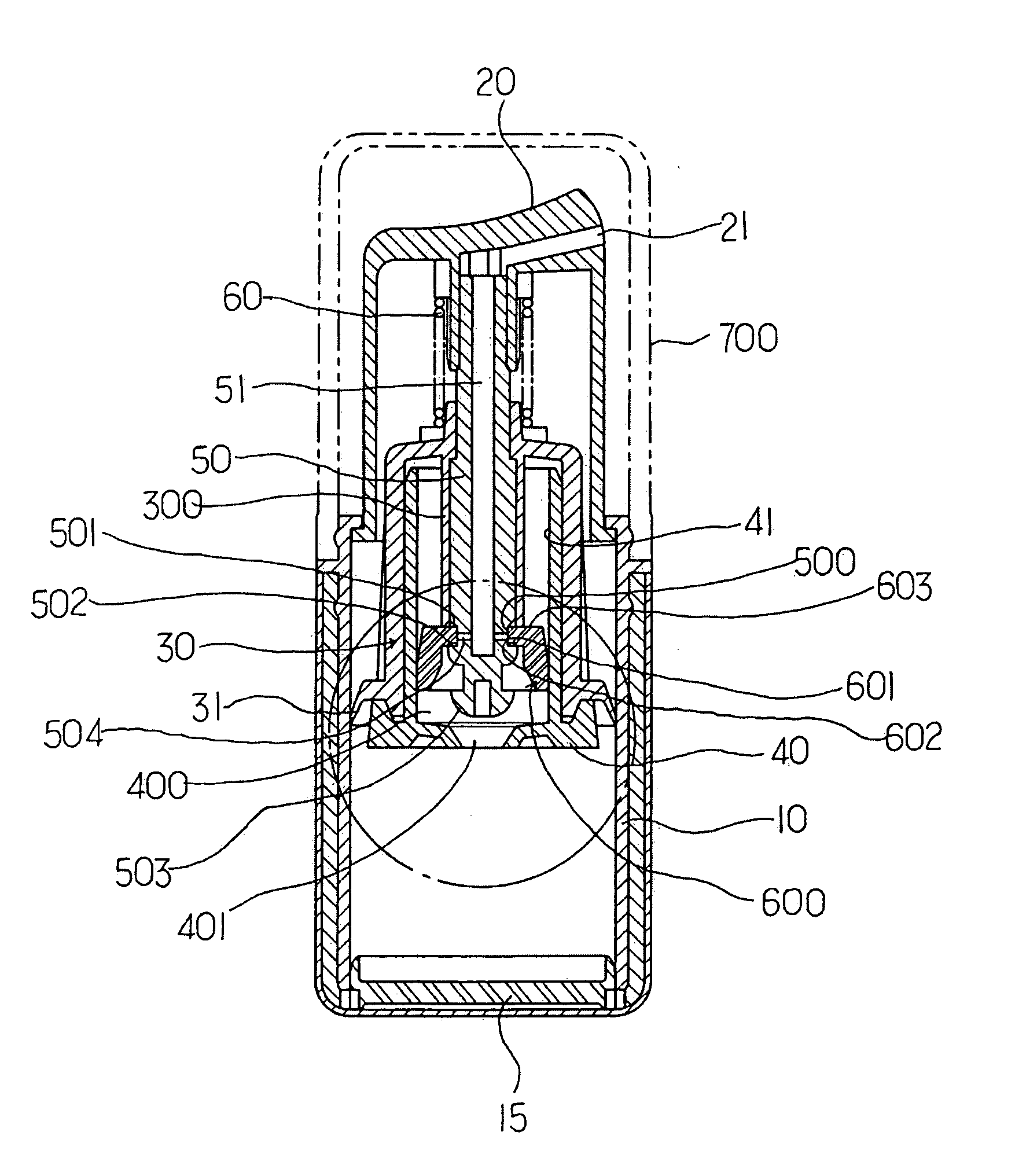
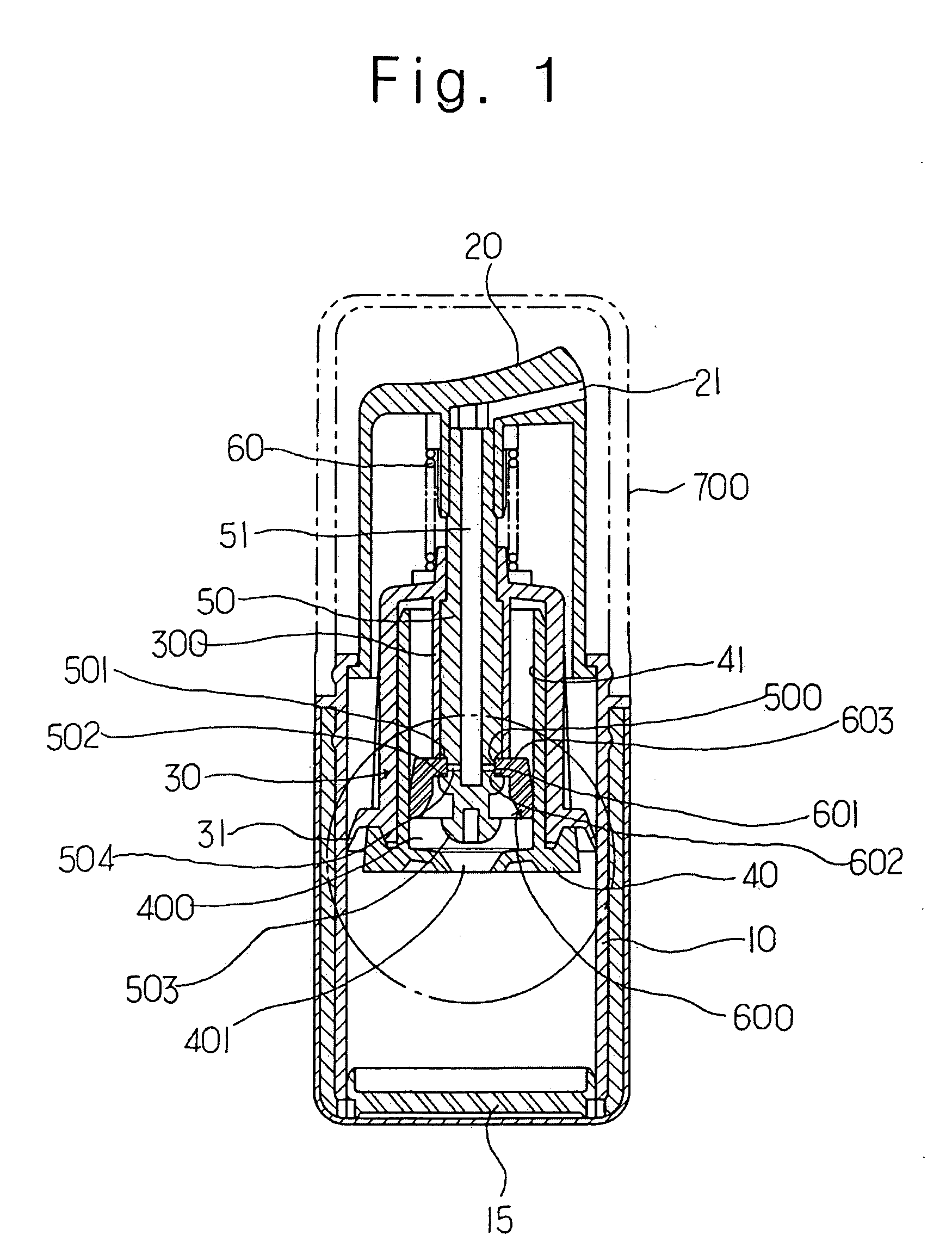
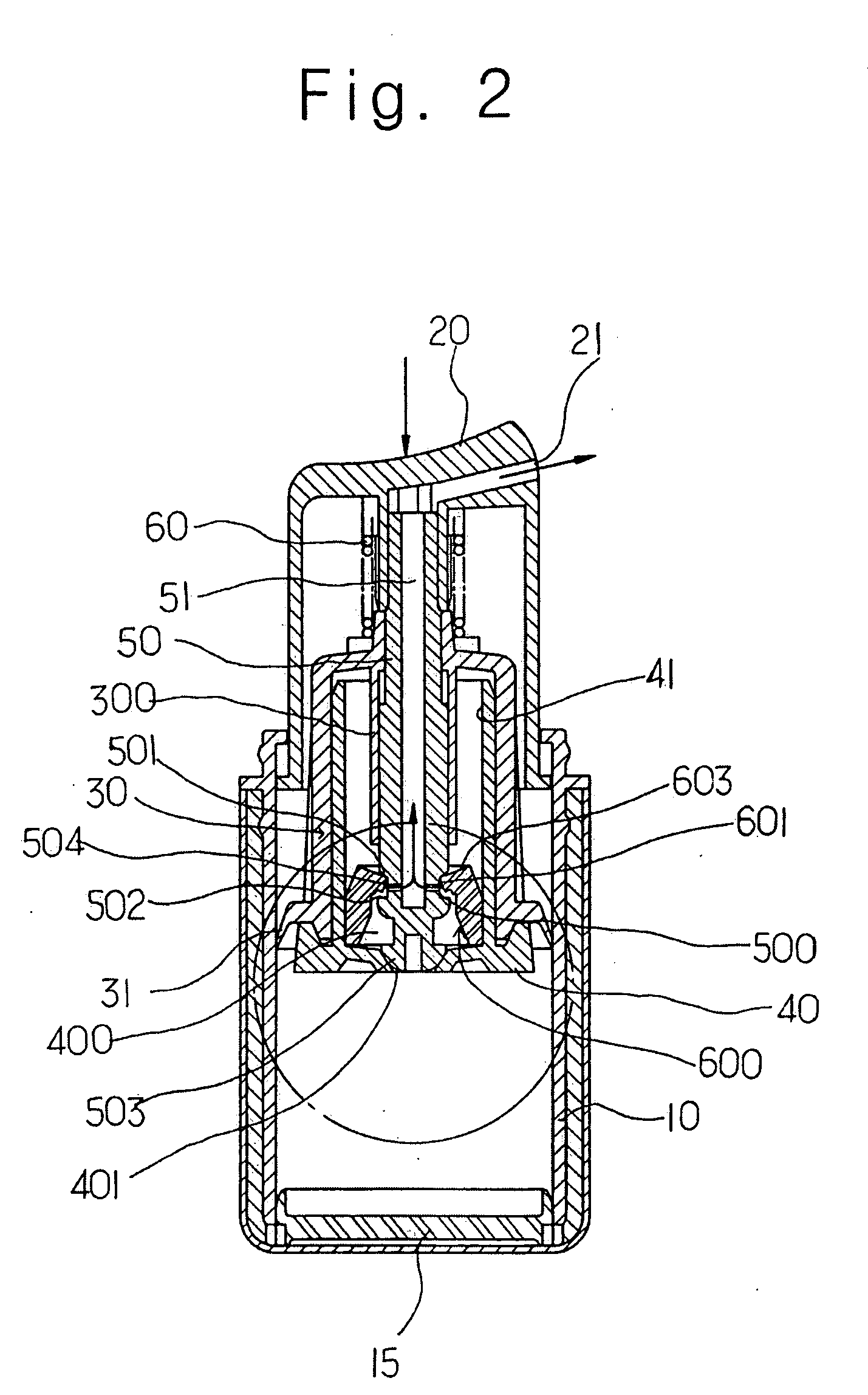
[0022] In a nozzle head lowering type vacuum cosmetics container comprised of a container 10 for containing liquid cosmetics, a sealing member 15 for sealing up the bottom surface of the container 10, a nozzle head 20 being assembled to the upper portion of the container 10 and having a nozzle hole 21, a piston member 30 built in...


PUM


Abstract

Disclosed is a constant discharge structure for a nozzle head lowering type vacuum cosmetics container for containing high functional cosmetics. The constant discharge structure includes a liquid collecting chamber having a liquid inflow hole in the lower portion of a piston support member mounted in the container, a groove having an inclined short jaw, a support jaw and a liquid inlet hole and an open/close unit for opening/closing the liquid inflow hole in the lower portion of a central shaft, an elastic pumping member being inserted into the groove of the shaft and including a hole having an inner wall for opening/closing the liquid inlet hole on a flat surface unit, and a cylinder incorporated inside a piston for supporting the central shaft.

Description

CLAIMING FOREIGN PRIORITY [0001] The applicant claims and requests a foreign priority, through the Paris Convention for the Protection of Industry Property, based on a patent application filed in the Republic of Korea (South Korea) with the filing date of Nov. 26, 2003, with the patent application No. 10-2003-0084414, by the applicant. (See the Attached Declaration) BACKGROUND OF THE INVENTION [0002] 1. Field of the Invention [0003] The present invention relates to a structure for discharging a constant amount of contents in a nozzle head lowering type vacuum cosmetics container for containing high functional cosmetics. [0004] 2. Description of the Related Art [0005] In general, high functional cosmetics such as essence, lotion and cream for preventing or reducing wrinkles, facilitating whitening and intercepting ultraviolet rays include vitamins or natural extracts as main ingredients. Such ingredients are sensitive. When the ingredients are exposed to air (oxygen) or sunlight (ult...

Claims


Application Information

Patent Timeline
Patent Type & Authority Applications(United States)
IPC IPC(8): A45D34/00B05B11/00B05B11/02B65D83/76
CPCA45D34/00B05B11/3001B05B11/3094B05B11/3066B05B11/3074B05B11/3026B05B11/1001B05B11/1026B05B11/1066B05B11/1074B05B11/1094
Inventor CHOI, HEE JINOH, YU KWANG
Owner CDR
Why Eureka
Try Eureka