Method and system for the analysis of co-localizations

a colocalization and analysis method technology, applied in the field of colocalization analysis, can solve the problems of inability to fault-tolerant and adaptive data acquisition, more cognitive problems than user-friendly benefits,

Active Publication Date: 2005-05-26
LEICA MICROSYSTEMS CMS GMBH
View PDF5 Cites 2 Cited by
  • Summary
  • Abstract
  • Description
  • Claims
  • Application Information

AI Technical Summary

Benefits of technology

[0020] In a simple expression of the method, the shape of this cone is to be considered symmetrical, the definition of the cone radius being linked to a reference intensity value that defines the absolute level. One skilled in the art can effect a concrete embodiment. In a more complex variant of the method, the position of all dye spectra is utilized. Using this prior knowledge, the cone can be “dented” in systematic fashion by giving greater weight to directions in the intensity spa...

Problems solved by technology

Methods and systems for sensing maximum information from a fluorescing microscopic specimen are encompassed, but fault-tolerant and adaptive data acquisition is not possible with this method.
The visualizati...

Method used


Image

  • Method and system for the analysis of co-localizations
  • Method and system for the analysis of co-localizations
  • Method and system for the analysis of co-localizations

Examples


Embodiment Construction

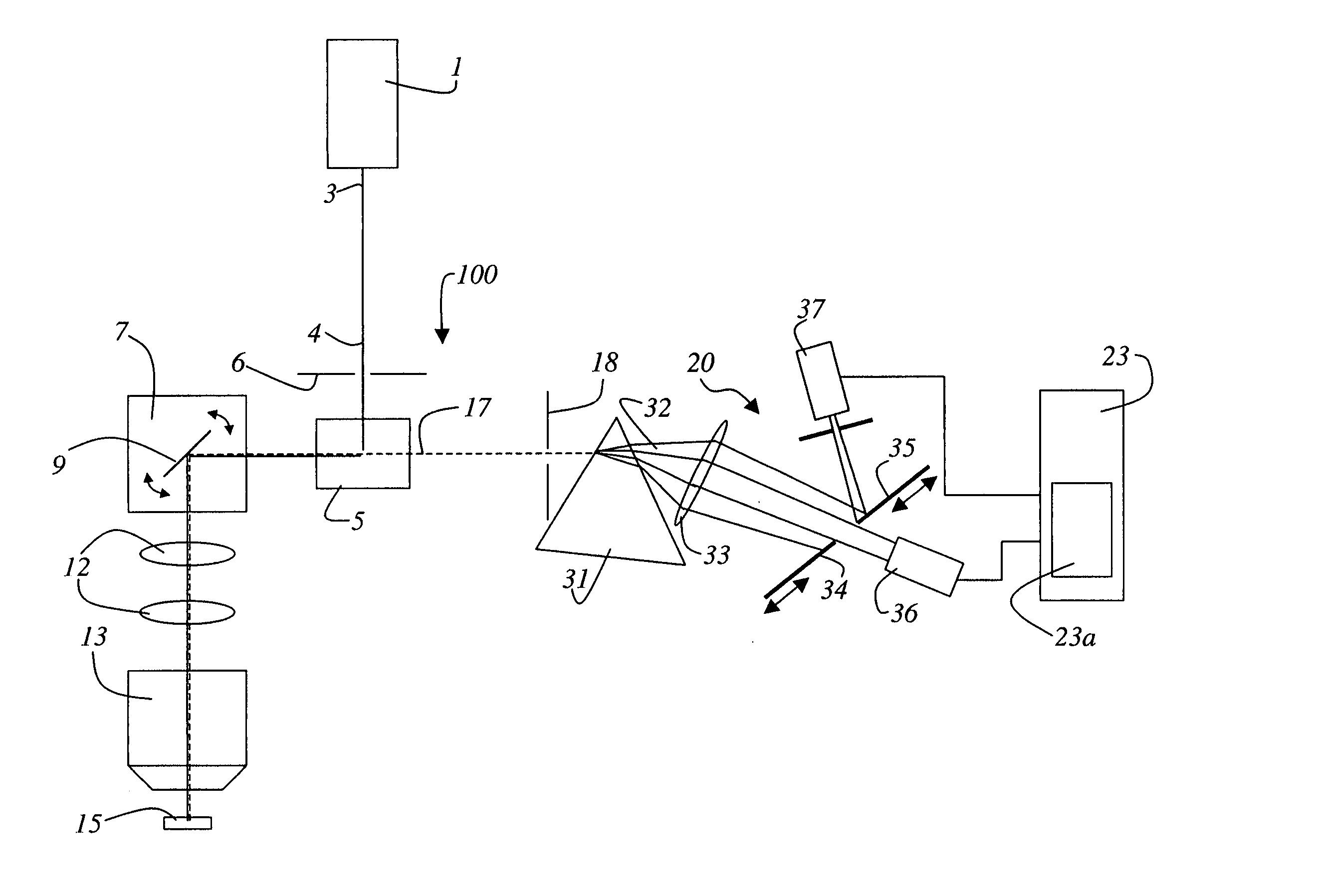
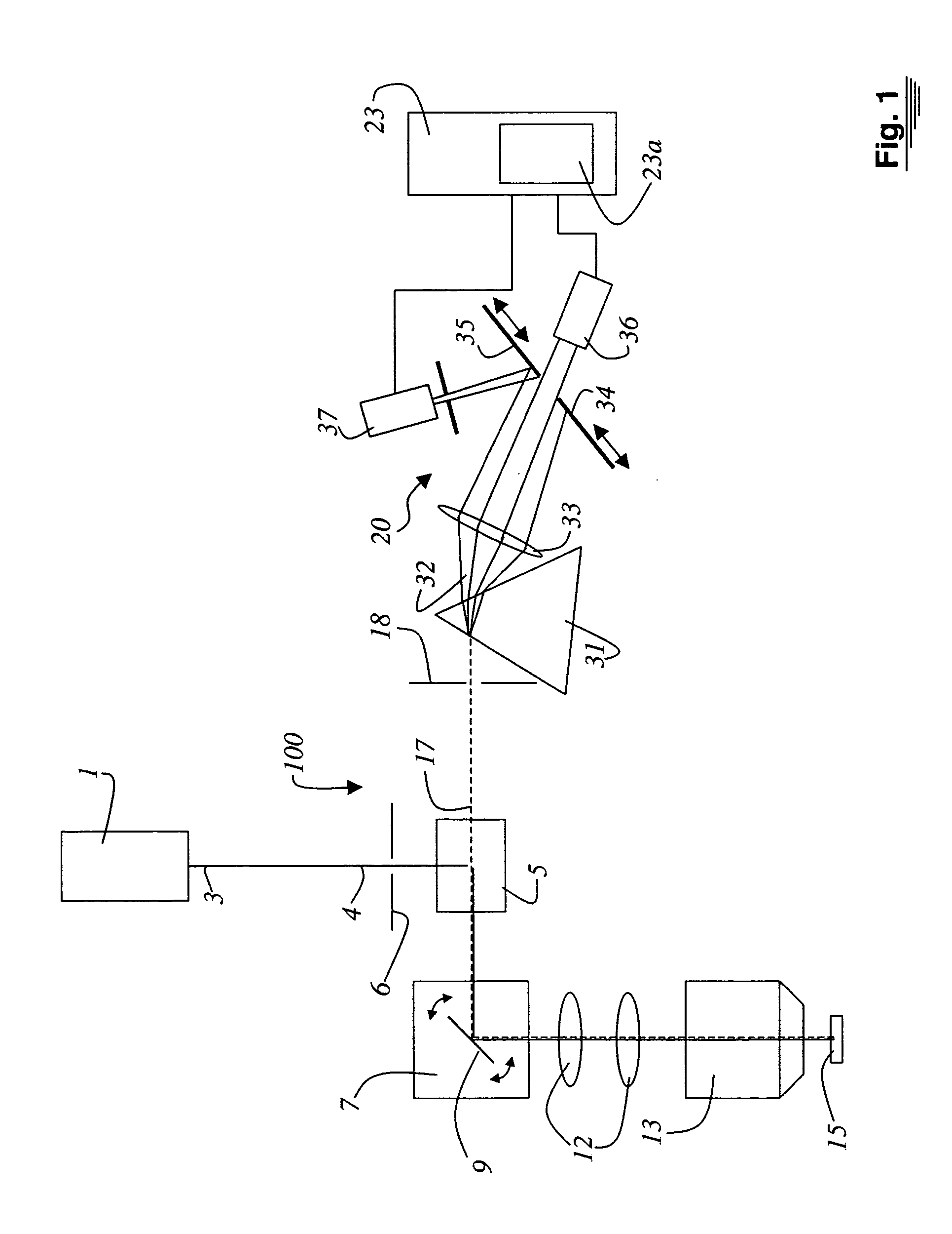
[0032]FIG. 1 schematically shows the exemplary embodiment of a confocal scanning microscope 100. This is not to be construed as a limitation of the invention, however, and one skilled in the art is well aware that the same components relevant to the present invention are also installed in differently constructed microscope systems, fluorometers, and cytometers. Illuminating light 3 coming from at least one illumination system 1 is directed by a beam splitter or a suitable deflection means 5 to a scanning module 7. Illuminating light 3 passes through an illumination pinhole 6 before it strikes deflection means 5. Scanning module 7 encompasses a gimbal-mounted scanning mirror 9 that guides illuminating light 3, through a scanning optical system 12 and a microscope optical system 13, over or through a specimen 15. In the case of non-transparent specimens 15, illuminating light 3 is guided over the specimen surface. With biological specimens 15 (preparations) or transparent specimens, i...


PUM


Abstract

A method and a system for the analysis of co-localizations of dyes present in a specimen (15) are disclosed. For that purpose, the various fluorescence spectra of all dyes present in the specimen (15) are determined. A tolerance region around each of the fluorescence spectra is selected. The spectra of the specimen (15), in which at least two dyes are present, are then acquired pixel by pixel. Those spectra that lie within the tolerance region around the fluorescence spectra are then calculated. A lambda vector is calculated for each pixel and assigned to a spectrum. Images can be outputted on the display in accordance with the assignment to the spectra.

Description

RELATED APPLICATIONS [0001] This application claims priority of the German patent application 103 55 150.6 which is incorporated by reference herein. FIELD OF THE INVENTION [0002] The invention concerns a method for the analysis of co-localizations. [0003] The invention further concerns a system for the analysis of co-localizations. BACKGROUND OF THE INVENTION [0004] German Patent Application DE 100 06 800.6 discloses an apparatus for the selection and detection of at least one spectral region of a spectrally spread light beam (SP module). Selection means that are embodied as sliders are provided in the spread-out light coming from the specimen to be examined, so as thereby to direct portions of the spread-out light beam onto various detectors. The signals of the detectors are then used for image generation. DE 100 06 800.6 does not disclose actuation of the sliders in such a way that rapid and reliable detection of a specific spectrum is possible. [0005] German Patent Application D...

Claims


Application Information

Patent Timeline
IPC IPC(8): G01N21/25G01N21/64G02B21/00H04N1/04
CPCG01N21/6428G01N21/6458G01N2201/1293G01N2021/6441G01N2021/6421
Inventor OLSCHEWSKI, FRANK
Owner LEICA MICROSYSTEMS CMS GMBH
Why Eureka
Try Eureka