

Large-area nanoenabled macroelectronic substrates and uses therefor
a macroelectronic substrate and nano-enabled technology, applied in nanoinformatics, instruments, transistors, etc., can solve the problems of limited success, difficult fabrication of high-performance tfts on plastics, limited application range of current technology, etc., and achieve enhanced carrier mobility and high performance
- Summary
- Abstract
- Description
- Claims
- Application Information
AI Technical Summary
Benefits of technology
Problems solved by technology
Method used
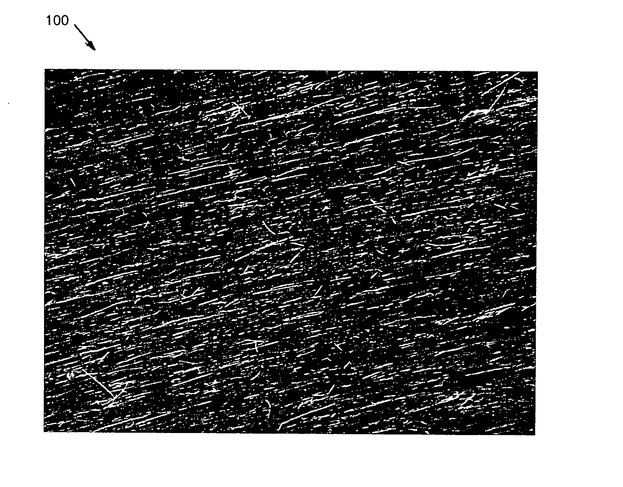
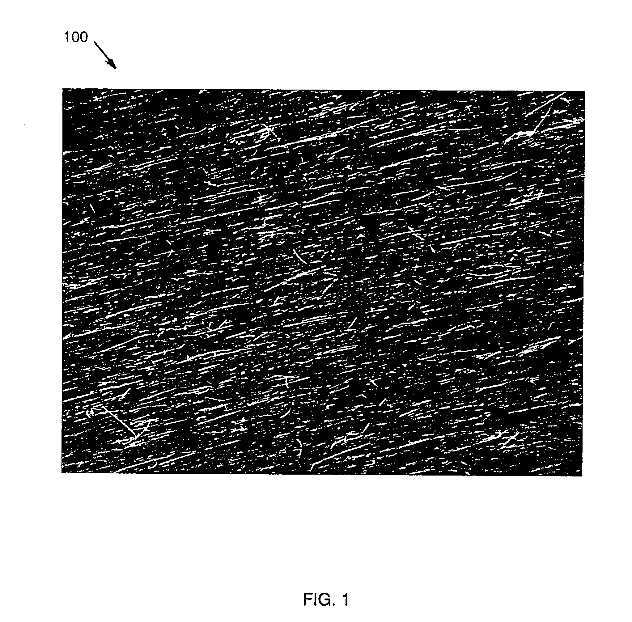
Image

Examples
Embodiment Construction
Introduction
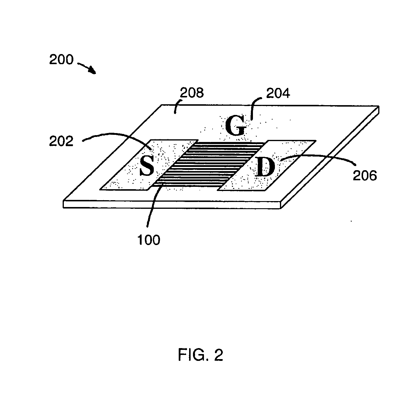
[0118] It should be appreciated that the particular implementations shown and described herein are examples of the invention and are not intended to otherwise limit the scope of the present invention in any way. Indeed, for the sake of brevity, conventional electronics, manufacturing, semiconductor devices, and nanowire (NW), nanorod, nanotube, and nanoribbon technologies and other functional aspects of the systems (and components of the individual operating components of the systems) may not be described in detail herein. Furthermore, for purposes of brevity, the invention is frequently described herein as pertaining to nanowires, and to a semiconductor transistor device. Moreover, while the number of nanowires and spacing of those nanowires are provided for the specific implementations discussed, the implementations are not intended to be limiting and a wide range of the number of nanowires and spacing can also be used. It should be appreciated that although nanowire...
PUM
| Property | Measurement | Unit |
|---|---|---|
| area | aaaaa | aaaaa |
| area | aaaaa | aaaaa |
| area | aaaaa | aaaaa |
Abstract
Description
Claims
Application Information