Demultiplexing device and display device using the same

a multi-layer display and multi-layer technology, applied in the direction of instruments, static indicating devices, etc., can solve the problems of insufficient data current programmed to the pixels, and the time for programming the data on the pixels is reduced, so as to reduce the number of data drive ics without reducing the data programming time

Active Publication Date: 2005-05-26
SAMSUNG DISPLAY CO LTD +1
View PDF34 Cites 92 Cited by
  • Summary
  • Abstract
  • Description
  • Claims
  • Application Information

AI Technical Summary

Benefits of technology

[0008] The present invention provides a demultiplexing device and a display device for reducing the number of data drive ICs without reducing the data programming time.

Problems solved by technology

Therefore, the data current is insufficiently programmed to the pixels since the time for programming the data on the pixels is reduced as compared to using no demultiplexer.

Method used


Image

  • Demultiplexing device and display device using the same
  • Demultiplexing device and display device using the same
  • Demultiplexing device and display device using the same

Examples


Embodiment Construction

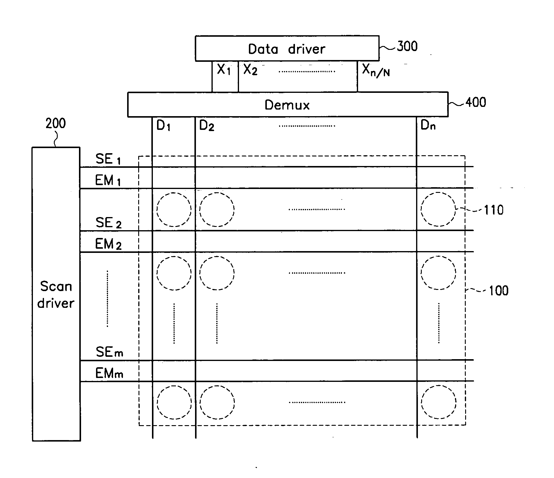
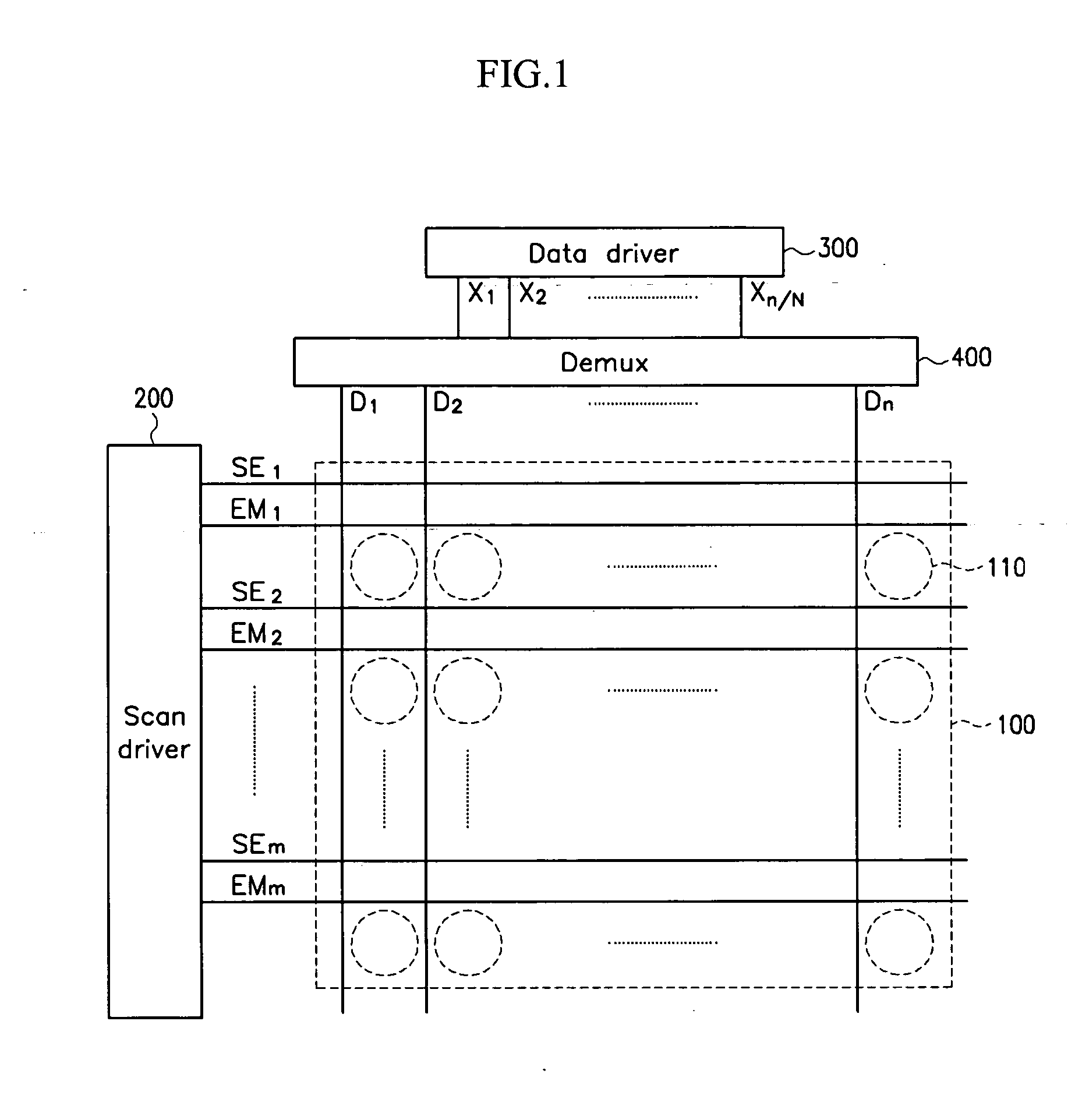
[0055] As shown in FIG. 1, the display device includes display region 100, scan driver 200, data driver 300, and demultiplex unit 400. A plurality of data lines D1 to Dn, a plurality of select scan lines SE1 to SEm, a plurality of emit scan lines EM1 to EMm, and a plurality of pixels 110 are formed on display region 100. Data lines D1 to Dn are extended in a column direction, and transmit data currents for displaying images to the pixels. Select scan lines SE1 to SEm and emit scan lines EM1 to EMm are extended in a row direction, and respectively transmit select signals and emit signals to the pixels. Each pixel is formed at a region defined by two adjacent data lines and two adjacent select scan lines, and the pixel includes a transistor for transmitting the data current provided by data line Dl in response to the select signal applied through select scan line SEj, and a display element for showing gray in response to the data current transmitted by the transistor.

[0056] Scan driv...


PUM


Abstract

In a display device, a demultiplexer is used to transmit a data current to a data line. The demultiplexer includes a plurality of sample/hold circuits for sampling the time-divided and sequentially input current and holding them to the data line. A plurality of data lines coupled to the demultiplexer are coupled to pixels of the same color, and hence, currents with different levels are transmitted to pixels of different colors. A sample/hold circuit for transmitting a higher level current uses a driving transistor having a larger ratio of a channel width and a channel length.

Description

CROSS REFERENCE TO RELATED APPLICATION [0001] This application claims priority to and the benefit of Korea Patent Application No. 10-2003-0084479 filed on Nov. 26, 2003 in the Korean Intellectual Property Office, the entire content of which is incorporated herein by reference. BACKGROUND OF THE INVENTION [0002] (a) Field of the Invention [0003] The present invention relates to a demultiplexing device and a display device using the same. More specifically, the present invention relates to a demultiplexing device for demultiplexing current using a sample / hold circuit. [0004] (b) Description of the Related Art [0005] A display device requires a gate drive integrated circuit (IC) for driving scan lines and a data drive IC for driving data lines. The data drive IC has output terminals corresponding to the number of data lines since it converts digital signals into analog signals and applies the analog signals to all the data lines. A plurality of data drive ICs are used to drive all the ...

Claims


Application Information

Patent Timeline
Patent Type & Authority Applications(United States)
IPC IPC(8): G09G3/30G09G3/20G09G3/32
CPCG09G3/20G09G3/325G09G3/3283G09G2310/0297G09G2300/0861G09G2310/0272G09G2300/0842G09G3/30
Inventor SHIN, DONG-YONG
Owner SAMSUNG DISPLAY CO LTD
Why Eureka
Try Eureka