Autofocus system

a technology of autofocus and luminance level, applied in the field of autofocus system, can solve the problems of inability to obtain value, malfunction of autofocus, excess and insufficiency of luminance level, etc., and achieve the effect of enabling the luminance level of video signal, performing surely and accurately, and changing the range of af area

Inactive Publication Date: 2005-05-26
FUJI PHOTO OPTICAL CO LTD
View PDF23 Cites 14 Cited by
  • Summary
  • Abstract
  • Description
  • Claims
  • Application Information

AI Technical Summary

Benefits of technology

[0021] According to the present invention, an object range of autofocus is arranged to coincide with an object range of exposure adjustment in the imaging device for AF for autofocus, thereby enabling a luminance level of a video signal of the AF area acquired for au

Problems solved by technology

For this reason, in the case where the object range of AF is limited to a part of the AF area in a screen, the large difference between the lightness of a subject outside the AF area and the lightness of the subject inside the AF area causes a

Method used


Image

  • Autofocus system
  • Autofocus system
  • Autofocus system

Examples


Embodiment Construction

[0033] The preferred embodiments of an autofocus system according to the present invention are described below with reference to accompanying drawings.

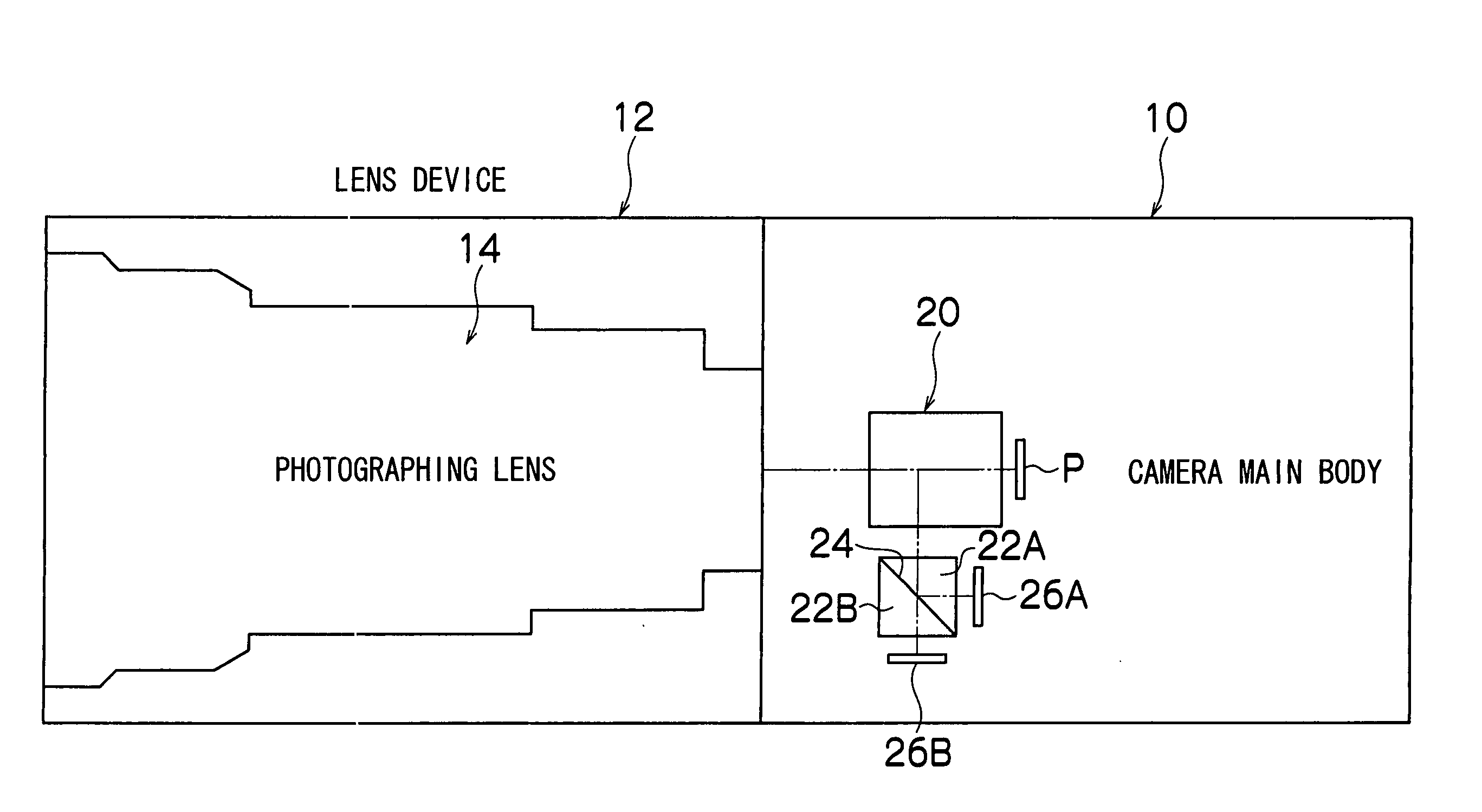
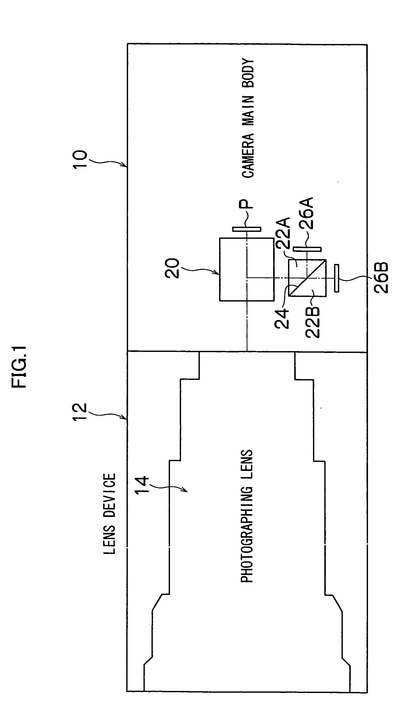
[0034]FIG. 1 is a schematic representation of a camera for photographing a moving picture, for example of a television camera, etc., to which the present invention is applied. The camera (television camera) shown in the figure comprises a lens interchangeable camera main body 10 and a lens device 12 mounted on the camera main body 10. The lens device 12 includes a photographing lens 14 (optical system) which comprises optical components, such as various fixed and movable lens groups and an iris, and a control device (control system, not shown) for electrically controlling the movable lens (group) and the iris of the photographing lens 14.

[0035] In the camera main body 10, a color separation optical system 20 (of which detailed configuration is not shown) is arranged and a subject light passing through the photographing lens 14 is de...


PUM


Abstract

Two imaging elements for AF, each having a different optical path length, are mounted to a camera main body. The automatic focus adjustment is performed based on the video signal of the AF area extracted by the gate circuits from the video signal acquired by the imaging elements. The electronic shutter function of the imaging elements is controlled based on the video signal of the AF area extracted by the gate circuits, so as to enable the exposure adjustment for the AF area to be performed.

Description

BACKGROUND OF THE INVENTION [0001] 1. Field of the Invention [0002] The present invention relates to an autofocus system and more particularly to an autofocus system which performs automatic adjustment of focus in combination of an AF of a contrast system applied for photographing a moving picture in a television camera, etc. or in combination of the AF of the contrast system and an AF of other system. [0003] 2. Description of the Related Art [0004] The autofocus (AF) system employed in a television camera or a video camera typically uses a contrast system. The contrast system extracts, by means of a filter, high frequency components from a video signal obtained by photographing a subject and evaluates a contrast level (sharpness) of the subject image based on the high frequency components. Also, the focus (focus lens) of a photographing lens is arranged to be controlled so as to enable the evaluated value (hereinafter referred to as the focus evaluation value) to be the maximum (lo...

Claims


Application Information

Patent Timeline
IPC IPC(8): G02B7/28G02B7/32G02B7/38H04N5/232
CPCG02B7/282G02B7/285G02B7/32G02B7/34H04N2007/145G02B7/38H04N5/23209H04N5/23212H04N5/23293G02B7/36H04N23/663H04N23/673H04N23/635
Inventor SASAKI, TADASHIOUCHI, SYUNICHIRO
Owner FUJI PHOTO OPTICAL CO LTD
Why Eureka
Try Eureka