Composite reflecting surface for linear LED array

Active Publication Date: 2005-05-26
WHELEN ENGINEERING COMPANY
View PDF11 Cites 57 Cited by
  • Summary
  • Abstract
  • Description
  • Claims
  • Application Information

AI Technical Summary

Benefits of technology

[0018] A further object of the present invention is to provide a new and improved composite reflecting surface that efficiently integrates the light output of a plurality of point source LEDs into a substantially uniform

Problems solved by technology

Losses are incurred each time light is reflected or passes through a lens.
Light that is not directed to reinforce the desired pattern is effectively lost.
Until recently, light-emitting diodes (LEDs) were extremely limited in the quantity and quality (candela vs. viewing angle) of light produced, rendering them unsuitable for many warning and illumination applications.
High-output LEDs have significantly greater luminous flux than previous LEDs, however, the total luminous flux from each LED (15-40 lumens) is still relatively small when compare

Method used


Image

  • Composite reflecting surface for linear LED array
  • Composite reflecting surface for linear LED array
  • Composite reflecting surface for linear LED array

Examples


Embodiment Construction

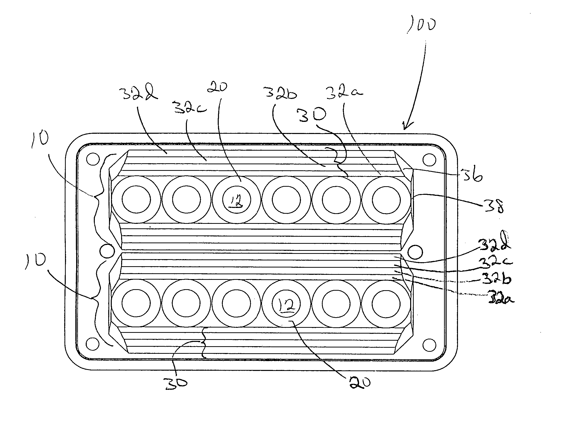
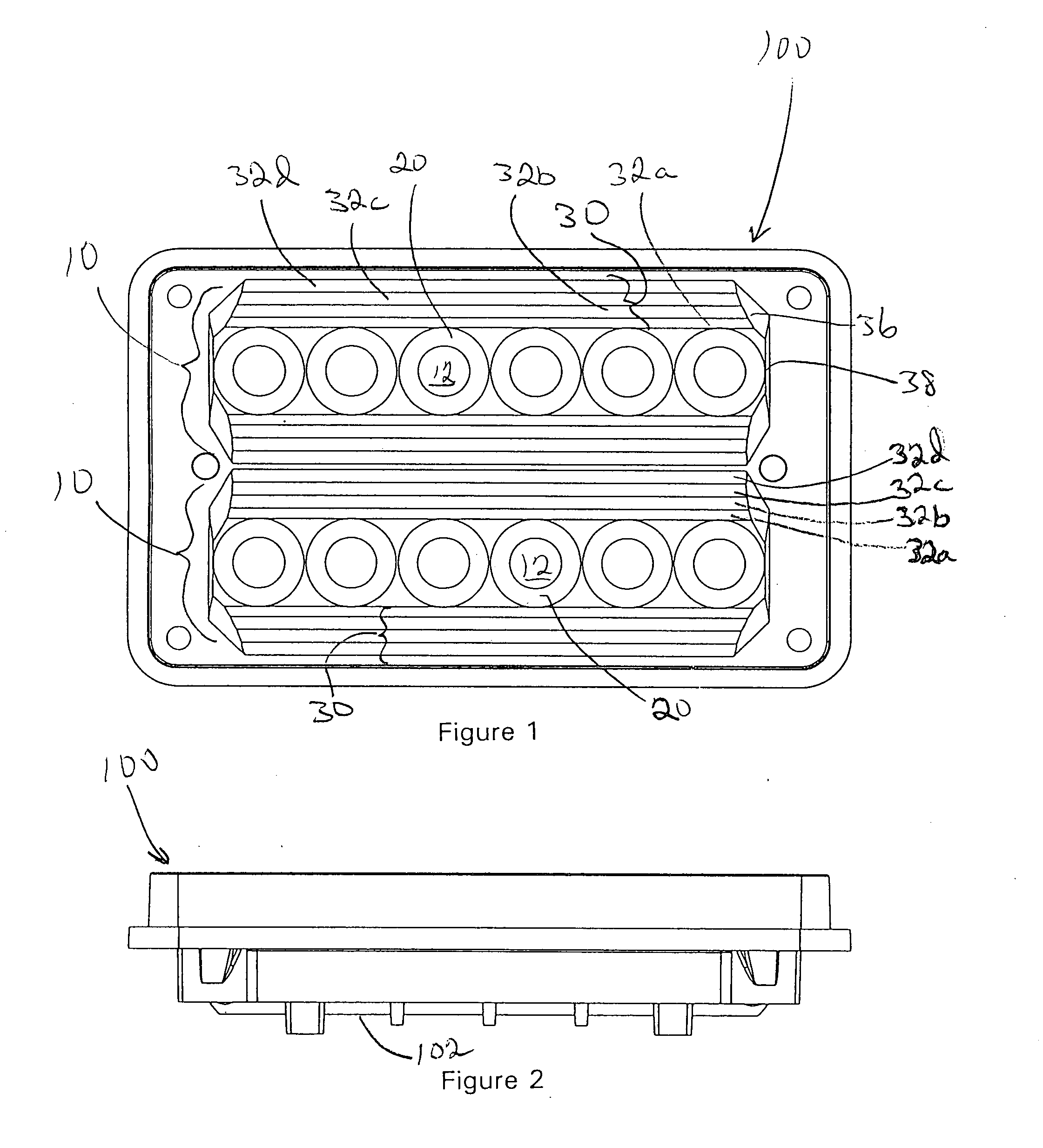
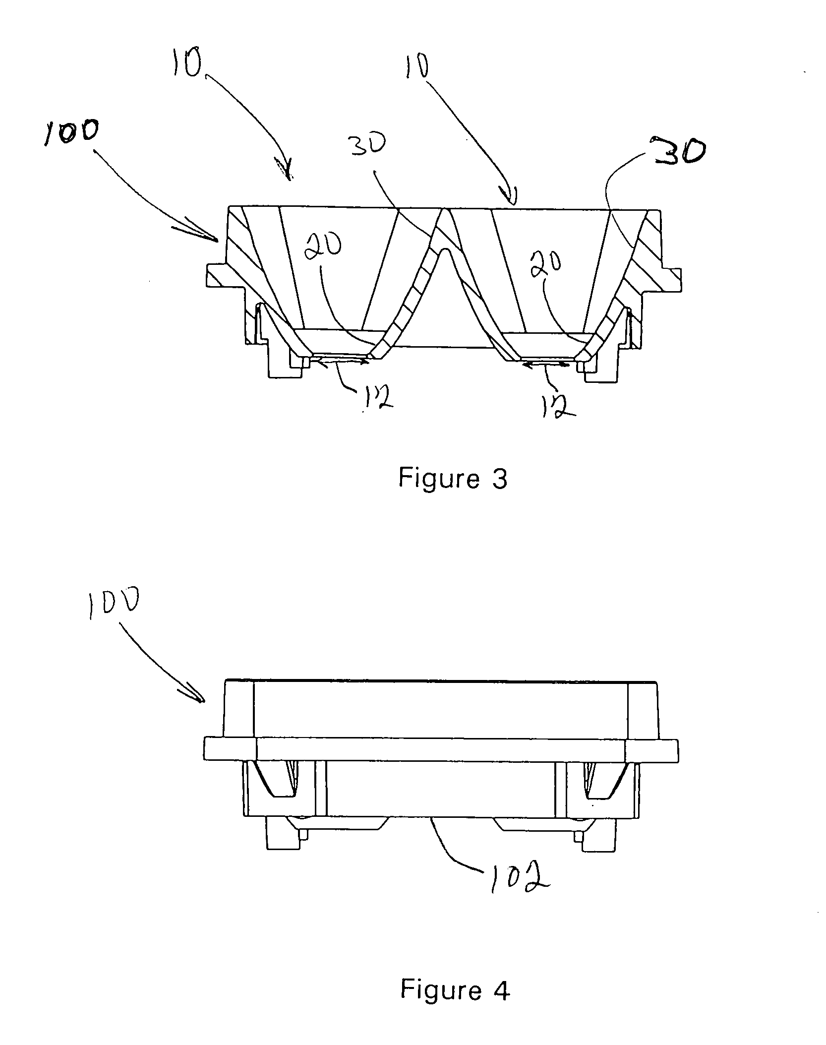
[0031] An exemplary embodiment of a composite reflecting surface in accordance with aspects of the present invention will now be described with reference to the figures. FIGS. 1-4 illustrate a reflector 100 incorporating two composite reflecting surfaces 10. The reflector 100 is for a warning light 200 including two linear arrays 106 of LEDs 108 (see FIG. 13). In this embodiment, the two linear arrays 106 are arranged parallel to each other and extending along the length of the rectangular reflector 100. The back side 102 of the reflector 100 defines locations for securing PC boards carrying the LEDs 108. A lens 104 covers the front of the assembly. A thermally conductive plastic heat sink 110 covers the back of the assembly and provides a thermal pathway for heat generated by LEDs 108.

[0032] The back side 102 of the reflector 100 also defines openings 12 for receiving the lenses and bodies of the surface-mount LEDs 108. The back side of the reflector surrounding the LED openings 1...


PUM


Abstract

A composite reflecting surface for a linear LED array incorporates a truncated circular parabolic reflector surrounding each LED and a trough axially above the circular parabolic reflectors defined between parallel longitudinal reflecting surfaces. The short circular parabolic reflectors collimate wide angle light from the LED into a direction parallel to the LED optical axis. The longitudinal reflecting surfaces are linear parabolic surfaces altered to improve the vertical spread of the light radiation pattern. Longitudinal convex ribs project inwardly from the basic linear parabolic shape. The convex shape of the ribs “sprays” the light incident upon it in a vertically spread pattern. The composite reflecting surface makes use of light from a linear array of LEDs that would otherwise be wasted.

Description

BACKGROUND OF THE INVENTION [0001] 1. Field of the Invention [0002] The present invention relates generally to warning light devices, and more particularly to a device for producing integrated directional light from a plurality of LED light sources. [0003] 2. Description of the Related Art [0004] Lights designed to serve illumination, warning or signaling functions must produce light of different intensity, duration and pattern. Within any broad category, such as warning lights, lights designed for a particular application, for example aircraft warning lights, may require a very different intensity and light pattern than a warning light designed for an emergency vehicle such as a police car or fire truck. [0005] The prior art contains numerous examples of alternative light sources, reflectors and lenses arranged to produce particular intensities and distributions of light suited for a particular purpose. Of primary concern to designers of lights are efficiency and accuracy. Efficien...

Claims


Application Information

Patent Timeline
IPC IPC(8): F21V1/00F21V7/06G02B17/06
CPCF21V7/0083F21V7/04F21V7/09F21Y2101/02G02B19/0028Y10S362/80G02B19/0066G02B19/0023F21Y2103/003F21Y2103/10F21Y2115/10
Inventor SMITH, TODD J.
Owner WHELEN ENGINEERING COMPANY
Why Eureka
Try Eureka