Apparatus and method for packet error correction

a packet error and error correction technology, applied in the field ofapparatus and a method for correcting packet errors, can solve the problems of low throughput, packet loss, and delay in rtp packet delivery and packet loss in the network, and achieve the effect of suppressing transmission of unnecessary retransmission requests

Inactive Publication Date: 2005-05-26
FUJITSU LTD
View PDF11 Cites 80 Cited by
  • Summary
  • Abstract
  • Description
  • Claims
  • Application Information

AI Technical Summary

Benefits of technology

[0022] In the light of the above problems, an object of the present invention is to provide a packet error correcting apparatus and method, which can regenerate video and voice with the most suitable delay time by that a packet receiv

Problems solved by technology

However, since RTP does not assure real-time data communication, there is possibility that the RTP packet may suffer delivery delay and packet loss in the network like other packets.
Accordingly, there is a disadvantage that when a packet loss or an error occurs, the decoder's side cannot maintain the quality in regeneration even if a high-quality data delivery process is performed.
However, TCP is reliable in error correction, but causes low throughput and large delay, so that the retransmission packet may be too late for the regeneration.
Accordingly, this becomes a problem when a real-time communication system is realized.
However, it cannot realize high-quality media transmission in a network environment in which a packet loss occurs in burst.
Use of FEC technique is effective in a network environment where the transmission rate is low but the error rate is high,

Method used


Image

  • Apparatus and method for packet error correction
  • Apparatus and method for packet error correction
  • Apparatus and method for packet error correction

Examples


first embodiment

A Description of First Embodiment

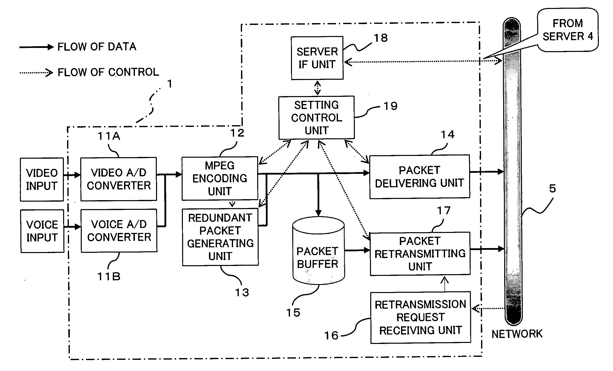
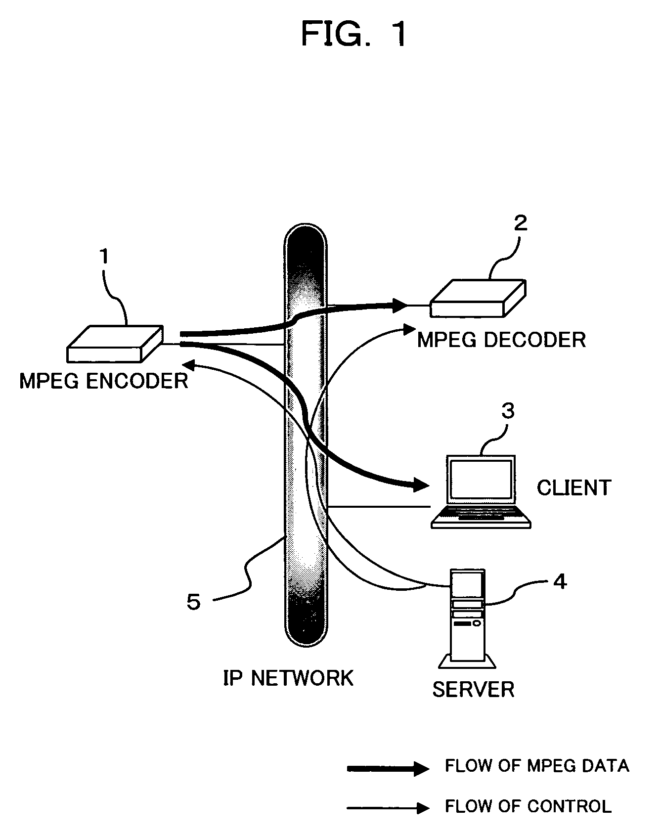
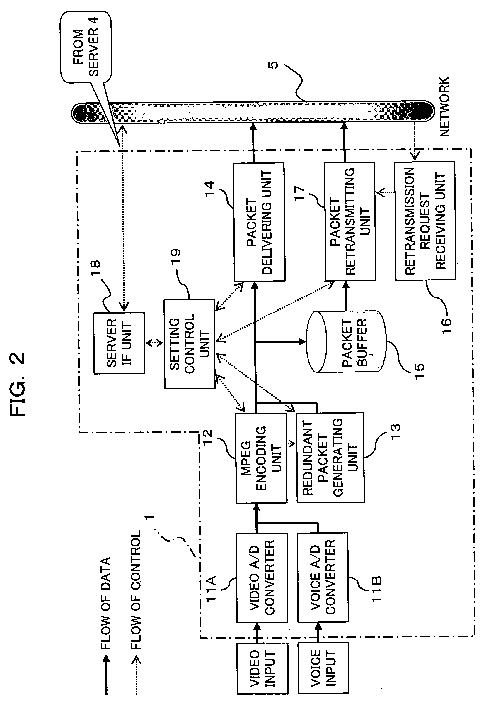
[0045]FIG. 1 is a block diagram showing a structure of a communication system to which an error correcting apparatus according to a first embodiment of this invention is applied. As shown in FIG. 1, the communication system of this embodiment is configured by connecting, to one another, an MPEG encoder 1 delivering live MPEG streaming data encapsulated in packets over an IP (Internet Protocol) network having high error rate as being a network 5, an MPEG decoder and / or a client terminal 3 receiving, decoding, displaying, and so forth the streaming data (packets) transmitted from the MPEG encoder 1, and a server 4 performing setting of and control on the encoding mode, a live delivery address, etc. of the MPEG encoder 1, the MPEG decoder 2 and the like.

[0046] In this system, the server 4 sets the encoding mode (MPEG 1, 2 or 4, the encoding bit rate, with or without voice, etc.) and a live-delivery address to the MPEG encoder 1. The server 4 also sets,...

second embodiment

B Description of Second Embodiment

[0084] In the above first embodiment, it is determined, according to a time interval of transmission of redundant packets, whether or not a retransmission request is immediately transmitted. However, there is possibility that the redundant packet is received immediately after even at a low rate, depending on (a number of) the lost packet. As shown in FIG. 5, for example, when one redundant packet (FEC packet) is transmitted for 10 MPEG packets (N=10), a packet having a number 1, 2, 11 or 12 is transmitted in the early stage, while a packet having a number 9, 10, 19 or 20 is transmitted in the later stage in a packet group that can be restored with one redundant packet. Accordingly, a packet having a number 1, 2, 11 or 12 and a packet having a number 9, 10, 19 or 20 largely differ from each other in time required until the redundant packet is received when the packet is lost.

[0085] In the MPEG decoder 2 (client 3) according to a second embodiment, t...

third embodiment

C Description of Third Embodiment

[0095] According to a third embodiment, when a part of MPEG packets delivered from the MPEG encoder 1 is lost, the MPEG decoder 2 (or client 3) changes the timing of transmission of a retransmission request to the MPEG encoder 1 according to a degree (the number of lost packets) of the loss of packets. Incidentally, the structures of the MPEG encoder 1 and the MPEG decoder 2 (client 3) are the same as or similar to those described above with reference to FIGS. 2 and 3 unless otherwise specifically mentioned. The operation of the MPEG decoder 1 is the same as or similar to that according to the first embodiment unless otherwise specifically mentioned.

[0096] The MPEG decoder 2 according to the third embodiment operates according to a flowchart (step S21 to S32) shown in, for example, FIG. 6. In this case, the MPEG decoder 2 receives a packet delivered over the network 5 by the packet receiving unit 21 (step S21), and determines whether the received pa...


PUM


Abstract

A packet error correcting apparatus comprises a retransmission request controlling unit controlling a timing of transmission of a retransmission request to a packet transmitting apparatus from a retransmission request transmitting unit according to whether an error correcting unit can restore the lost packet within a predetermined time period when loss of the packet is detected. In a packet receiving apparatus such as a decoder or the like supporting both FEC and ARQ, it is possible to control a timing of transmission of a retransmission request when packet loss occurs, thereby to regenerate video and/or voice with the most suitable delay time while suppressing transmission of unnecessary retransmission requests.

Description

BACKGROUND OF THE INVENTION [0001] (1) Field of the Invention [0002] The present invention relates to an apparatus and a method for correcting packet error, that is, a technique improving error resistance when packet data (hereinafter referred to simply as “packets”) transmitted from an encoder (packet transmitting apparatus) is received by a decoder in network environments where there occur a lot of packet losses (errors) such as the Internet or the like, for example. Particularly, the present invention relates to a technique suitable for use to improve the error resistance in streaming data transfer. [0003] (2) Description of Related Art [0004] Recently, there is an increasing demand for data communications of image data, voice data and the like via various communication means including Internet communications. Particularly, services by means of streaming delivery system in data transfer over the Internet are increasing as services of recent data communications. In the streaming d...

Claims


Application Information

Patent Timeline
IPC IPC(8): H04L1/18H04L1/16H04L12/26H04L12/70H04L29/06H04N7/24H04N21/438H04N21/6375H04N21/6377H04N21/643H04N21/658
CPCH04L1/1819H04L29/06027H04N21/4382H04N21/6375H04L65/80H04N21/64322H04N21/658H04N19/89H04L65/607H04N21/6377H04L65/70H04L1/18H04L65/1101
Inventor MIURA, TSUYOSHIFUJITA, SHIN
Owner FUJITSU LTD
Why Eureka
Try Eureka